|
Welcome to . . .
|
| Home |
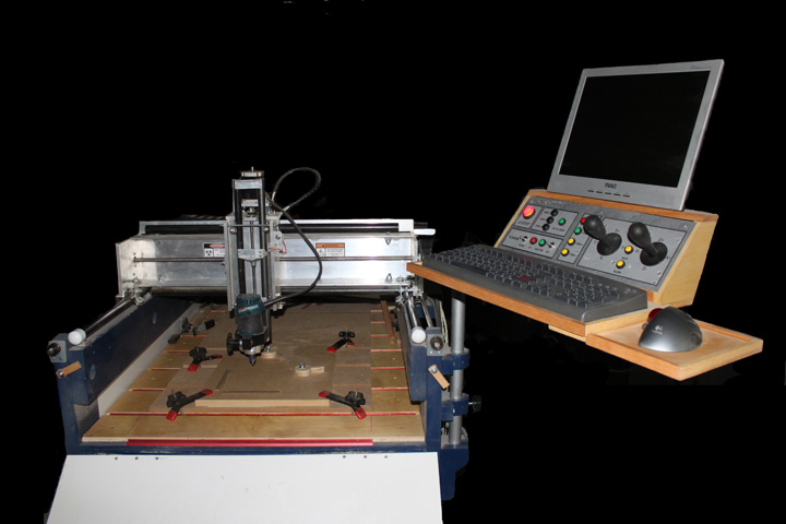
Winter 2009. This website is a log of my building experience with making a computer controlled (CNC) router table. The picture above is how it turned out, and I have cut complicated instrument panels for airplanes in aluminum, engraved brass in tiny lettering, shaped many different pieces of various plastics, and cut and carved many different species of wood with it. This website is in the form of a log, i.e., told in the chronological order of building it. This project began in early 2009 and was completed in about 6 months of part-time work, not counting the arm and spindle upgrades that came later. The purpose of this log is to share info and experience with other CNC builders about this project, just as I have gotten so much from theirs - so, welcome! Comments may be sent to gary at liming daught org. When I started, I spent quite a bit of time online studying what's available and asking advice. Considering my budget, and hoping for the best, I settled on the following:
Many of these decisions were dependent upon studying the above websites, as well as reading volumes of forum posts on the CNCZone.com website. Lots of good stuff there, still going through much of it. Although that may sound like a lot of work, it is really quite inspirational to see what other builders have done on both very tight budgets and ones without any apparent limit. The Solsylva plans were received in just 2 days from ordering - they are nice plans, and David Steele certainly has a lot of hard-won experience with these things that he shares in the plans. His plans call out three differently sized CNC machines to be made with materials you can get from your local big box home supply store, but yet allows for upgraded parts to substituted for better speed or accuracy. I've already decided to upgrade some of the parts. I began obtaining the materials. Some of the parts I've collected so far:
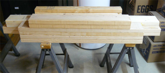
Fig.1 Fig. 1 is a stack of carefully selected #2 framing lumber cut as per the plans for the basic table. It consists of 2x6's, except for three 2x4 pieces on the top rear. I hope to cut some light aluminum parts with this set-up, but the elastic properties of wood say that I should consider making some of the more critical parts with metal. I may also add a bottom shelf to the table - it would provide a place for the electronics and could enhance stability of the table. Besides, you can never have enough horizontal surface in the workshop!
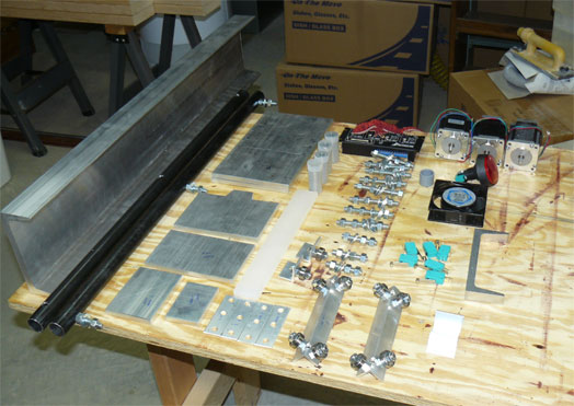
Fig. 2 One substitution shown on the left in Fig. 2 is the C-shaped 6061 aluminum Y gantry, next to the two black pipe rails, already drilled for attachment with the studs. (Black pipe is commonly sold for water or gas lines at hardware stores.) The plans originally called for a 2x6 gantry. To the top right of the rails are the stacked carriage side plates, the carriage top and bottom, and some other plates. This aluminum came from a local metals dealer, Shapiro Supply. Other aluminum pieces not shown are some 1/8 x 1 x 1 angle stock, and some 1/8 x 1 flat stock available at the hardware store. The white bar in the middle is some high density polyethylene stock, cut from a 3/8 kitchen cutting board from Walmart. On top of that are the tubes of the 608 roller bearings (the kind used in skateboards) from Vxb.com. Note: Quality control on these is not great. Out of the two batches I bought, several in each batch were not good. Take each one and put it on a bolt or rod matching the ID, and roll it with a few pounds of pressure on it. If it feels crunchy or anything other than very smooth, pitch it. In the end, I ended up buying two batches of them which was enough for the whole table with a few spares left. The black unit above them is the Gecko 540 stepper controller, with the toy gecko on top that came with the unit. The G540 is a bit pricey but a very elegant piece, combining some smart drivers which has things like 1/10 micro stepping, miswire protection, isolation from the computer, speed optimization, and compensation for things like middle band resonance of the steppers, and a built in break-out-box - this has connections for things like limit switches, E-stop button, and home switches that tie into it as well as the stepper motors. In turn, this unit is tied to the power supply for the steppers, and interfaces to a PC parallel port cable. Under the Gecko driver in Figure 2 is a line of studs cut from 3/8 allthread rod (allthread is the common threaded rod you can buy from a hardware store) with hardware that is used to mount the black pipe rails. Three of the studs are already on one of the Y rails in the photo, the rest are for the other Y rail and both of the X rails. Just under them are the Y rail trucks that I've already made from the aluminum angle stock with nuts, bolts, and bearings. The light green objects are some nice roller-levered limit switches (75 cents each from Gateway). On top of them is a box fan for the power supply, and an e-button, or emergency switch that was made for pounding on an arcade game ($4.95 from Gateway) On top of that are the three Xylotex 425 oz-in stepper motors.
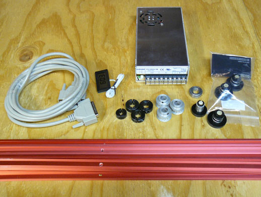
Fig. 3 Some more parts: on the left is a M/F DB25 straight through 6 ft cable to connect the computer's parallel port to the 540. I got this from Show Me Cables - they are tested with all 25 pins wired straight thru, and a shield connected to each connector's casing. (Beware - not all "printer cables" are wired the same or use all 25 wires. If in doubt, spend a moment to make sure all 25 pins are present and go straight through, or you will spend a lot of time later wonder why things aren't working!) To the right of it is a cheap ($3) temperature display and sensor. It comes powered by a hearing aid battery (1.5v) but I will replace that with its own power supply. With the sensors that cheap, I might just get 1 for each stepper, 1 for the power supply, one for the router, and 1 for the Gecko driver. Speaking of power supplies, the silver box is for the steppers, a Potrans 24V 12 amp switching power supply I got from MJPA. I might want to replace that with a 48V homemade linear later, but for now it was less than half the cost of just the transformer for a linear supply. Under the power supply are some black clamping collars for the 1/2 inch and 3/8 ACME rod ends. To the right of them are the 1/2 inch pulleys, and to the right of those are some DumpsterCNC leadnuts. Just above the leadnuts is one of the 1-1/8 OD bearings for the 1/2 inch ACME's. Another note: I originally got the aluminum pulleys shown above - I should have gotten the steel ones like I ended up doing later. There are very few threads for the set screws to work with in the aluminum pulleys, and they must be very tight. At the bottom of the picture is some T-slot track for the bed. This should make holding down the target piece much easier. These are usually kind of expensive, but Grizzly had them cheapest, although I had to drill and countersink them myself.
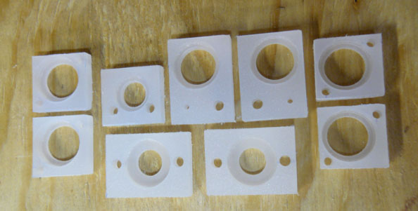
Fig. 4 Above are some of the polycarbonate bearing plates. Interesting material, easy to machine with Forstner bits. Sometime Real Soon Now it will be nice to have a CNC machine make these from a drawing! Many builders with more experience say the first CNC machine you build is supplanted by the next one, made by parts from your first build!
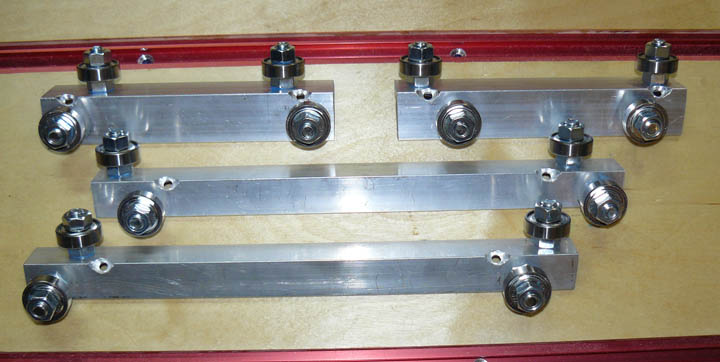
Fig. 5 Above are the Y and Z axis trucks, ready to mount, made from aluminum angle, bolts and bearings. |