|
|
FSR Probe Bed Leveling |
|
This is a separate page to document the building and use of Force Sensitive Resistors (FSRs) with a small processor front end to replace microswitches as a proximity or "probe" switch on a 3D printer. This is the result of an idea by Johann Rochall to replace the probe microswitch by wiring FSRs into one of the A/D ports on the Arduino, and updating the firmware to support it. However, no code changes are needed to the printer's firmware if they can be used in a way to simulate a microswitch closure. Therefore, further collaborative work amongst Wing Wong, John Socha-Leialoha, Ian Lee, Jr. and others on the Google Group "Delta Robot 3d Printers" called for the use of a small front end processor to do that simulation. I am only documenting this approach in a single place for others. John Socha-Leialoha went on to create and manufacture a custom board for this and sold some - check the above named group for availability if you want to go that way.
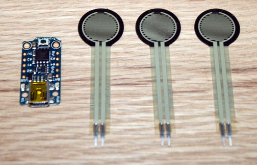
Fig. 1 Above shows the FSRs and the Trinket. These FSRs are available from a variety of places on-line - I think I got mine from Adafruit for $7 apiece. To wire these you must exercise care as the pins on the leads are very fragile - use as little force as possible on them and definitely heatsink them if you solder or heatshrink around them as the plastic melts very easily. One method is to wire-wrap the pins if you have that tool and 32 gauge wire available - but in any case, just use caution. The Trinket I also got from Adafruit for $8, so you are looking at $29 for the above 4 components. There are 3 and 5 volt versions of the Trinket, so to make life simple in this case just get the 5 volt one. To use this with the Arduino IDE, you must download the specific drivers for it - it has a USB port on it, but no UART style serial interface emulation on board. Go to the Adafruit site and go through the "Introducing Trinket" tutorial, but wait to install the drivers as is described on their support forum that is specific to the Trinket - they are updated and work better. Note that even though I got the drivers to work, I always got a weird error message after loading that seems to indicate it did not load, but it did indeed load the program without a problem, so ignore the error. The other three wires coming from the Trinket plugs into any 3D printer control board that expects to see a microswitch closure when the nozzle touches down on the platen. Most of the software like Marlin, Repetier, etc expect the switch to be wired Normally Closed, so the software emulates that and allows this to be used. At this writing, I am using a RAMPS card, and wired a connector to match the Zmin input.
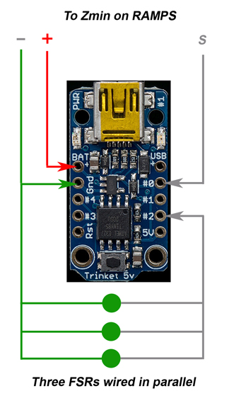
Fig. 2 Above is a picture of the Arduino Trinket and how it is wired. The three wires on the top go into the RAMPS Zmin input that has +5v, Gnd, and Signal (S), but can be used on any card expecting a microswitch wired normally closed (NC.) The Trinket program you want to load you may get here. Again, thanks to Ian Lee, John Socha-Leialoha, and Wing Wong for their work in providing this.
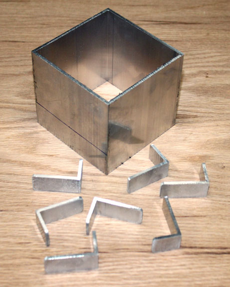
Fig. 3 Here are some mounting brackets I made from the piece of .125 walled square aluminum tubing shown at the top. It was simply convenient to make these like this at the time, but there are now several FSR mounting bracket designs on Thingiverse or other 3d model repository that you can print to do the same job.
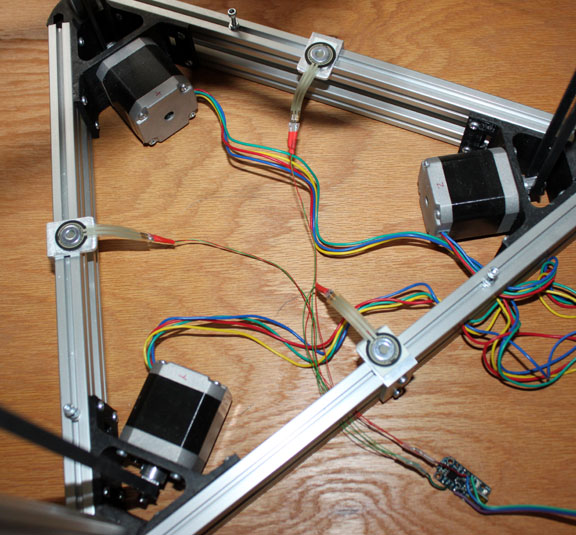
Fig. 4 Here are FSRs mounted in my machine, and they work very well. The FSRs are mounted to the brackets with double stick foam tape, and a 3/8 dia. washer is taped in the center of each FSR (using non-foam double stick tape) to place the weight of the platen on just the sensor surface. The platen is held in place by the tall cap head screws that are tightened in place on the rails when the platen is on - just enough to stop the platen from moving horizontally in the X and Y direction, but freely allowing it to move in the Z direction so that the probe can easily work. The programmed Trinket is shown below. I encapsulated it with some clear 3/4 in shrinkwrap tubing after taking the photo - protected, but you can still see the onboard LED flash when the probe is triggered. There are also rail mounting options for it on Thingiverse you can print. Once you have everything wired and the code compiled and loaded into the Trinket, you should see the power LED on the Trinket turn on, and then if you lightly tap the platen, you should see the other on-board LED flash as shown below. The total weight of the platen (bed) on the FSRs will affect the sensitivity. If the sensor triggers too easily, you can degrade the sensitivity of the device by changing the .95 number on line 133 of the code down to .82 or so. My aluminum platen is a bit heavy, so I found that .88 worked best for me. The idea here is that you want to be able to trigger the probe with as light as touch as possible in order to save wear on your probe and effector assembly, but not such that normal movement of the stepper and rails causes it to trigger. Another way to solve this is to add some vibration dampeners for the steppers, which have the added benefit of making your machine run very quietly. I got mine here. Although I am sure it is obvious, since there is actually contact being made at the surface of the platen, you should make sure the nozzle tip and the platen surface are clean before starting any auto-calibration sequence.
Above is a short video showing a light tapping with my fingernail on the aluminum platen, and the resulting LED flash on the Trinket to the right. |
|