

Frisby-Haas No Slot Flaperon
The 801 design calls for a rather large slot to be cut into both sides of the fuselage to allow the flap control rod to be attached to the tail of the flaperons as shown on an existing 801 below:
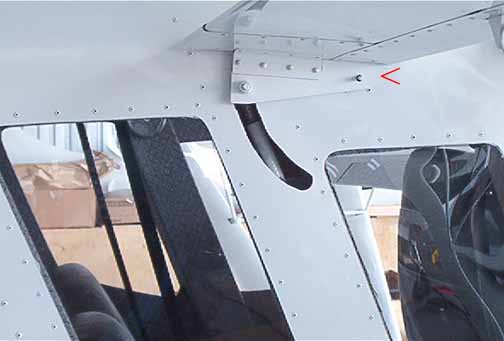
Photo courtesy Jim Frisby
This design has the hinge point, shown next to the red arrow under the flap, made from a 1/4 inch rod butt welded to a small plate that is riveted to the fuselage skin. The flap control rod, shown in the shadow of the slot above, is bolted to the other end of the flap horn. This design is simple and lightweight, but leaves the slot open in the side of the aircraft.
Jim Frisby, a fellow builder in Alaska, had a great idea by passing a tube welded to the horn through the fuselage at the pivot point, which would slide over another tube of smaller diameter that has a connecting horn welded to it. Once the tubes were inserted and in place, a hole would drilled and bolted through both of them, locking them in place. The tubes would be supported by a nylon pillow block bearing, and there would be no slot needed.
This idea was first realized in practice by Ben Haas, another 801 builder in Jackson Hole, Wyoming. The pieces needed are:
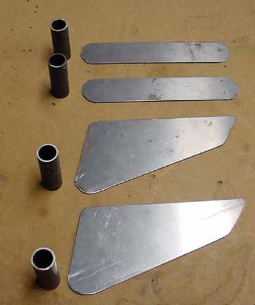
The steel is 4130 chromium-molybdenum, and the plates are 1/16 or 3/32 inch thick, and the front tubes are 3/4 inch OD and the back tubes are 5/8 OD, and they just slide inside one another if you sand or turn the smaller ones down a bit.
Dimensions of the pieces - the tubes are both 2 inches long, and will be cut back later. The inside arms are 1 1/4 by 6 3/4 inches, which allows for some extra length for the bend that will take place later. The outside arms are first cut in the trapezoidal shape of the aluminum piece supplied with the kit, and then a diagonal is trimmed off it, leaving room for the "L" stiffener under the flap. Final dimensions are 6 1/8 along the top, 3 1/4 along the left side (at the rounded part's greatest dimension), 6 inches from the furthest left side to the right bottom curve, and the smallest side is 1 1/8.
After cutting them out and filing them, the tubes are TIG welded to their respective horn, as shown in the upper picture below:
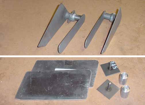
The bottom picture shows the parts used for the flap control in the kit supplied design, and the top shows the parts for the No Slot Flap design. The top parts as shown weigh 19.2 oz.. and the bottom parts as shown weighs 8.4 oz, so the difference is only going to be about 10.8 oz.
After the flap is mounted on the wing per the manual, the pivot point can be determined precisely and holes are drilled to rivet the large horn to the flap end with the tube centered on the pivot point, as shown below in a picture from Haiko Eichler, another builder using this design.
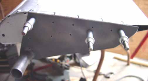
Photo courtesy Haiko Eichler
A 7/8 inch hole will be drilled in the fuselage for the outside tube to pass through at the pivot point of the flap, and the pillow block is then be bolted in place. The distance between the pillow block and the outside arm will depend on where the side of the flap comes in relationship to the fuselage. The pillow block nylon insert moves like an eyeball to allow the fuselage skin to be at a slightly different angle than the outside arm. Once the outside arm is drilled onto the flap, it can be marked and trimmed back to fit the contour of the flap precisely.
When the outside arm is in place and the flap is freely rotating on the pillow block, the tube of the inside arm is placed inside the tube of the outside arm, and the vertical flap control rod is clamped to the end of the inside arm, and the whole assembly checked for free movement. At this time, the inside arm may be bent in toward the cabin wall to allow for the control rod, but measure the distance between the rod and the pivot (the manual calls for 135mm) after making this bend.
Once the attachment point of the vertical rod to the inside arm is drilled, it may be desirable to trim back the length of the inside arm, as well as trim back the length of both the inner and outer tubes so that the arm doesn't protrude from the cabin wall any more than needed.. The important thing is to make sure the full and free movement of the flaperons are being realized, and that this is reflected in the full movement of the control stick. Once everything is fitted and checked, and both the flaps and the stick are in neutral up right position, a hole is drilled through both the inner and outer tubes, and an AN3 bolt inserted with a castle nut/cotter pin that fixes the angle of the arms in place.
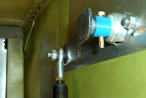
Photo courtesy Ben Haas
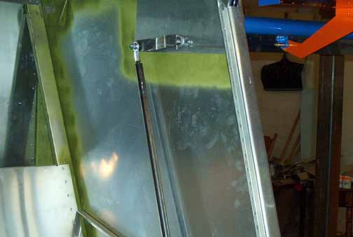
Photo courtesy Ben Haas
Another shot showing the vertical rod connecting to the inside arm, the mounted pivot block, and the painted flap suspended by its support arms. Note that the flap is supported by the wing, so there is little weight on the pillow block - it just acts as a pivot. The vertical rod is in exactly the same position it would have been in the kit design, but the cover will need to be extended a bit to cover the pivot point.
![]()
![]()
Images on this website are either Copyright Zenith Aircraft Company and used by permission or are copyright Gary Liming