

Electrical
March 15, 2001
I bought and finished reading Bob Nuckoll's Aeroelectric Connection, available at his website, www.aeroelectric.com. Very good discussions and tips there.
His idea of putting diodes across the inductive loads, like the solenoids (contactors, I mean) in order to ground out the transients in the first place will definitely be done. Also, he provides an overvoltage protection device that I will incorporate in the electrical system.
His best thing, though, is his idea of an "essential" bus - one that is put in play should the primary (alternator) power fail. I think I'll be restructuring the bus around this - allowing those things that are critical to the flight to continue on battery until landing. Knowing the amp-hours of the battery and the drain of the devices allows you to be comfortable with the remaining time to fly under a power failure.
January 15, 2002
Well, enough time has elapsed, and it is getting cold in the garage on some days so it is time to finalize the electrical schematic. Modifying some of the sample designs from Aeroelectric connection, I have a prelimnary schematic, which is reproduced below.
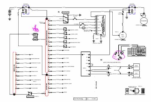
In addition, I have a wiring schedule, which is a spreadsheet that has a line describing every wire. Each line has a designator, pin connection (if any,) gauge, length, amps, diagram #, and status. So far, there is 416 feet of wire called out, and I haven't gotten to the engine yet! There are a lot of wires, so having a list like that will be very useful when it comes time to cut and crimp.
January 23, 2002
Finished the fuse block tray, which is arguably the heart of the electrical system. Here, power comes in from the alternator and the battery, and is distributed to the various electrical devices on the aircraft. If a short should develop, there is enough power distributed to burn and melt the wires, possibly causing the cabin to full with toxic fumes or cause a fire, so each wire must be protected from this kind of overload. In this case, each wire will have a fuse in its circuit to melt well after a normal load, but long before the wires are in danger.
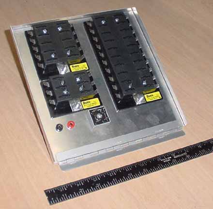
The large fuse block is the main distribution bus, the medium one is the essential bus, and the small one is the battery (always on) bus. Each block is attached with small bolts and nylok nuts. There are several empty (spare) fuse positions on each block, so there is some expandability. The other side of the hinge will attach to the flange under the instrument panel, so the whole tray can drop down and forward for easy access. The slight walls of the tray help to stiffen the whole assembly.
All the wires will be run to wire supports by the hinge and bundled so there is minimum movement of the wires when the panel rotates. The two test points are lines brought out through a resistor from the alternator - from this point, most alternator problems can be diagnosed. This makes standing outside next to a spinning propeller with a test meter unnecessary, which sounds like a very good idea to me! Next to the test points is a bridge rectifier of which one diode segment is used to tie the main bus to the essential bus. With this tray I can begin the wiring if it gets too cold to work in the garage. Weight as shown, 17.3 oz.
August 23, 2002
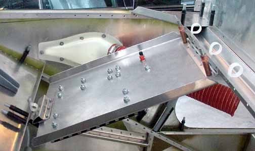
I should have waited to make the tray, as the first one wasn't quite long enough, so I made another one and installed it forward of the instrument panel as shown above. The white nylon cable clips are to help route the wires, and the latch is made up of a steel plate that is riveted to the firewall stiffener that has two more nylon cable clips back to back. I then bent a piece of aluminum and riveted it to the end of the tray in just the right location so that it fits snugly in between the clips when "the tray is in its upright and locked position." It seems to hold well. I got this idea from a similar latch at Michel Therrien's website.
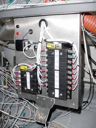
Here is what it looks like when dropped for access. After getting it in place, I changed my mind about the latch, and instead used a Camloc fastener for a more positive latch. Also, I added the UMA lighting inverter that is driven by the dimmer, mounted on the other side of the panel. Also, I mounted the B&C alternator controller back there for easier access. Everything can be seen easily, and all the wires are labeled as shown below.
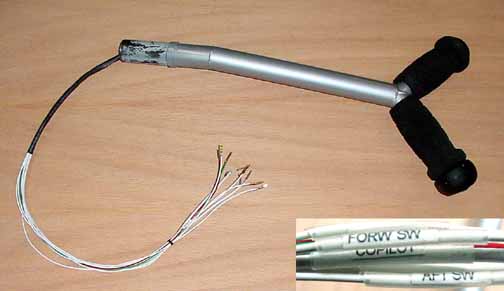
Here the stick has been painted to match the instrument panel, and the grips are on, and the switches are wired. Those switches are really tedious to wire. On the right seat grip there is a push to talk (PTT) only, and on the left seat grip, there is a PTT and four top micro switches. The fore and aft switches control the trim, and the other two I haven't decided on yet. All are brought out to a connector that will be in place once the wires are routed through the stick assembly. Each wire is labeled by slipping some clear 3/32" shrink wrap over the wire, and then inserting a plain paper label, and shrinking it down. The labels are created from the wire book list, which is just a word processing document printed at 6 pt Arial font on an ink jet printer. Each of the wire names are cut out to fit the shrink wrap. In the picture above, the crimp pins for the DB9 connector are also on, ready to be inserted in the DB9 shell. All the wires will be labeled this way. The hard part is remembering to slip some shrink wrap over the wire BEFORE crimping a connector on! (At least, that is what I've heard... ;^)
![]()
![]()
Images on this website are either Copyright Zenith Aircraft Company and used by permission or are copyright Gary Liming