|
|
|
|
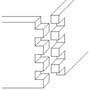
Fig. 1 Image courtesy WikiMedia Commons, Drawn by Luigi Zanasi This is a build log about making a jig for wood joinery in a way called a "finger" joint, shown above. An older term for it is "box" joint because back before the days of cardboard, plastic, and other high tech shipping containers, things were commonly packaged in wooden boxes, and this kind of joint was usually used to form them. If they weren't burned to keep someone warm, many of these boxes still survive in antique stores today. Since the fingers of the joint are usually straight, I have also seen it referred to as a "comb" joint. The beauty of this joint is that if you have a quick way to make them, it makes the construction of cases, drawers, boxes, and many other objects very simple. If you need a 10.5 x 8.75 box, you just cut two pieces of wood at each of those lengths, run the ends through the jig, and you've got your box at those dimensions. With today's glues, they are also incredibly strong - most resulting joints will fail on the wood itself before the joint will fail. I also think they give a give nice appearance to the finished work, something that says you made the effort to "get it right." There are many types of jigs that you can use to create this joint. Some are no more than a peg, the exact width of the finger, protruding from a fence that is used to position the end of the fingered board as it goes across the sawblade. The sawblade must also cut the same exact width as the finger, and a different blade width (like a dado blade) and a different peg must be used for each different width of the fingers. The most problematic with this "fence peg" jig is that it takes a lot of set-up to get things just right, and they are easy to mess up the joint - I know I've wasted material doing it this way. The philosopher said "Know Thyself" and by now I know myself pretty well. I have learned that if a given technique is difficult to do, or it is likely to screw up a part in which I've already invested time and materials, I probably won't even use it to begin with. Now, you can call me lazy, unskilled, or a host of other adjectives, but dealing with this by name calling doesn't help anything. However, if I have taken steps to make a successful result be more likely, I feel better about doing it, and it gets done. This idea takes form in so many different ways throughout my shop. Make things easy to clean up and it gets cleaned up. Make things easy to put away and they get put away. Make things easy to find and they get used. Anyway, enough philosophy, but the whole idea of a jig is to position or hold material in such a way as to ensure the outcome will be successful, no matter how much of a klutz I am. Whether or not I will actually use it depends on how easy it is to use.
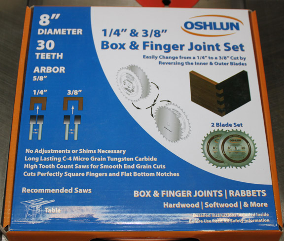
Fig. 2 The first rule of ease of use is to simplify the procedure. IMHO, first and foremost in this case has nothing to do with the jig, but is to eliminate having to fiddle with dado blades. Toward that end, I bought for under $60 (that was a while ago, it could be more now) an Oshlun set of two blades that combine to produce either a 1/4 inch kerf, or a 3/8 inch kerf. Since this represents the majority of the finger sizes I plan to use, this helps a lot. They are quite precise - the kerf on these measured .250 and .375 just like you want them to be with no fiddling or test cuts. There are more expensive ones out there, but I have to say these work very nicely. I can still use dado blades for other sizes, but this is a big improvment in my book. Next, a jig to position the wood in front of the blade. The more sophisticated finger joint jigs out there have a number of features, and the first one I stumbled across that looked good to me was from Matthias Wandel on his Woodgears website. Now, before I go any further, let me say that I really like his website and have spent many hours there, and he is one of the most clever woodworkers out there. I really appreciate his scientific approach to things - a case in point is his comparison of the superior strength of finger joints versus dove tail joints, well demonstrated here. I have bought several of his plans, and they are excellent. I also bought his gear design software, which is also exactly what I wanted for that purpose as well. Matthias calls the jig his Screw Advance Box Joint Jig Version 2, and if you are interested in this, you should take a look at his website. Below are some pictures and comments about how mine turned out.
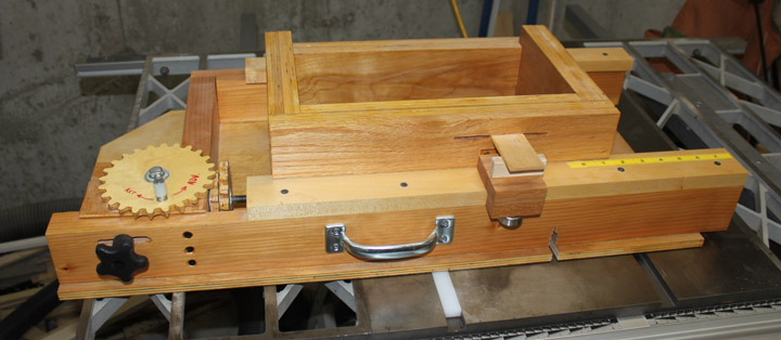
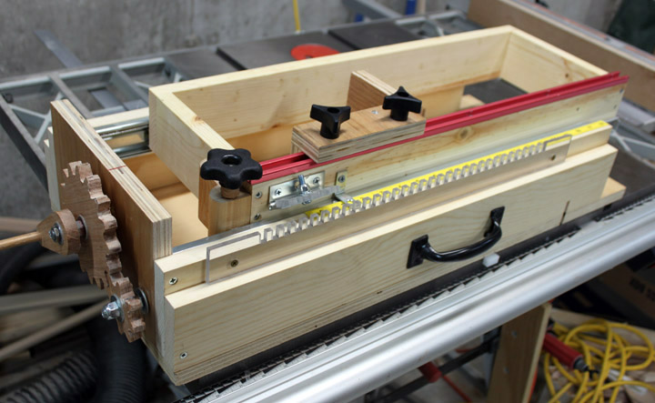
Fig. 3 The way this jig works is by clamping two boards vertically in the lower right hand corner of the open box area on top of the jig. This open box is called the carriage, and moves left to right by turning the crank on the large gear. When the carriage is in position, the jig is grasped by its front handle and slid into the sawblade, making the cut for the fingers. The carriage is then moved to the next position which is determined by moving the gears, and so on. Take a look at Matthias' videos for a better description. Matthias' plans are great. I pretty much built mine just like the plans called for, so it went together very quickly. He provides a cut list and a bill of materials that makes getting everything together a breeze. I don't think I bought any wood for it- just made it from pieces on hand and only had to buy a handful of hardware. I had the UHMW plastic for the mitre slot runner on hand as well.
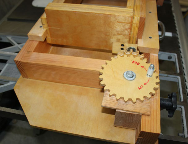
Fig. 4 A couple of times I wanted to move the carriage the wrong way, so marking the gear with a direction indicator helped, even if my lettering is a bit crude. For the crank handle, its just a nylon spacer on a bolt with some nylock nuts. The large gear sits on a plywood "table" to make it more stable when cranking, and I did put the recommended Teflon tape between the table and the gear to make it turn smoother. The black knob on the right allows the table to slide into the drive gear and comes off to help swap out larger or smaller gears. You can see the carriage rides on wooden rails - the left rail is just a piece of wood inserted in a dado on the side of the carriage, and the right is the same idea, only the rail is cut at an angle. The reason for the angle is to provide a tight fit along the movement axis with only a small amount of force to pull it against the rail, and this happens quite well. All in all, one of the criticisms I have seen with this is the idea that the wood would swell and stick over time, but I have to say I didn't really notice that. Nevertheless, there is quite a bit of friction that results with all that surface area in contact. I did try applying wax, and a few other forms of lubricant to the runners to mitigate this, but there is still some friction to overcome.
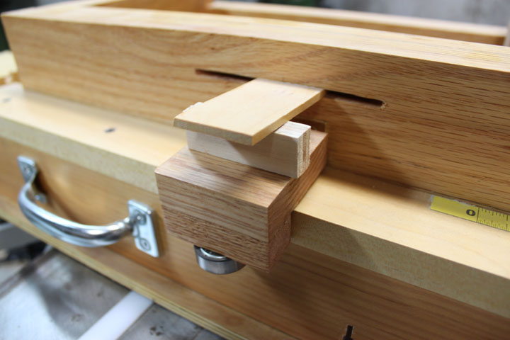
Fig. 5 This is the mechanism that pulls the carriage onto the angled rail to take up any play in the carriage movement. At first glance at the plans, the idea of using a wooden spring seemed a bit clunky to me, but it actually works quite well in practice. The top piece of wood in the slot is tapped into place over the hinged arm, pressing down on the arm. This presses the ball bearing against the front of the sled, pulling the carriage forward while still allowing it to move left to right. The hardest part of the build by far is the gears. I have a CNC machine and used it to cut out each one, but only in 2D profile. These gears are at a 90 degree angle to each other, so each gear tooth must be shaped with a compound angle on each side. Once cut by the CNC in profile, I did use Matthias' method of sanding them on a table tilted at the specified angle. Even then, I had to make each gear a couple of times to get them to work well together. I believe that if the main gear was mounted vertically instead of horizontally, the gears would be much easier to make and be a much smoother mechanism, even if it would require a mount to rise up above the jig and some way to accommodate the various sized gears. It might also make seeing the gear position a little harder than just looking down on them. The other problem I ran into was the combination of gear meshing and carriage friction made the forces on the drive gear and threaded drive rod great enough that occasionally in the middle of a cut, the ball bearing in its wooden housing would slip a bit out of position, which directly affected the accuracy of the cut for that tooth and all remaining ones. This is so slight that you don't notice it until it is time to put the joint together to check the fit. In fact, it took me a while to find what the problem was. There are two screws to tighten the wood around the bearing, but you can only tighten them so much. After stripping the screws on the first one, I replaced it with another bearing mount like what the plans shows, but I began to think that I needed to machine some kind of collar to keep the bearing from pulling out. This was the point I began entertaining a different approach.
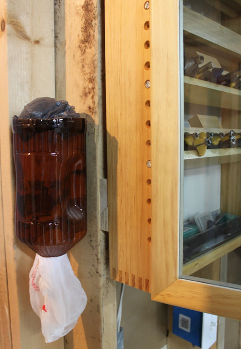
Fig. 6 Even with the above issues, I did make a few things with the jig. Above shows a cabinet for my router bits where I used finger joints cut on the Woodgears jig for the corners. The router bit shelves can be adjusted and tilted forward as shown. This made a nice, satisfying cabinet for them - I used the design from Shopnotes #86. (On the left is a holder for shopping bags made from the plastic bottle of a nice Canadian Adult Beverage with its top and bottom cut off, and screwed onto a stud.) The problems I found with the Woodgears jig I am sure could be overcome with some tinkering, but that means I found myself being reluctant to use it, wondering if there might still be a better way. That was when I ran across Stumpy Nubs' website who also sells plans, one of which is also a box joint jig. Now, before I go any further, let me also say that I really like Stumpy's website and his videos are very funny, entertaining, eagerly anticipated, and I think he has a great sense of humor. Don't let his self-effacing jokes obscure the cleverness of his designs, though - he also has many interesting ideas to share. Stumpy's plans are also sketchup pages, but the lack of video of the unit being built or in operation makes me think you really need to watch the Woodgears videos before building Stumpy's jig. Stumpy's video on the jig is limited to what is presented on his show, so it is constrained by a narrow time window and the need to entertain as well as inform. Also, to be fair, it should be noted that Stumpy had the advantage of making and using the Woodgears box joint jig before designing his, whereas Matthias certainly did not have that advantage. Like Isaac Newton said, "If I have seen far, it was because I was standing on the shoulders of giants." Stumpy's plans also lack a cut list and a bill of materials (BOM.) Some might say that the lack of a BOM is no big deal, and they are right - it is no big deal to make a list of the parts you used, with sizes and maybe even a column for their source and how much they cost, but if so, why wasn't one included with the plans? I think many woodworkers buy the plans to simply reproduce the unit shown in he video. The plans shouldn't be indefinite about what was used or what size pieces were chosen for what was built. It is okay to say that some parts may be lengthened or shorten to accommodate more or less capacity, etc., but if the builder wants to reproduce the unit that is shown in the video in order to assure the advertised results, that info is very helpful. Likewise, a cut sheet lets you instantly see how much plywood or other materials you will need. Knowing that it will only take a quarter sheet of plywood (or whatever it needs) helps me to cost out the thing when I am making the build decision. Availability and choice of materials is often pretty important in the overall success of some projects, so specifying them is an important way of sharing in what works/doesn't work. Okay, I know the plans are a just a few bucks, and I probably expect too much from them, but I definitely have to give Woodgears the nod on this one, since these items were included with their plans and I find them very useful. Anyway, in spite of this minor issue, it looks like Stumpy's jig is the one I will be using. Note From the Future: (Imagine your favorite time metaphor here - sands falling in an hour glass, pages of a calendar being blown away one at time, me cleaning my dust collection system, etc...) Since I wrote this, Stumpy has changed his plans format for new projects. They are now plain ole .pdf files instead of sketchup files, which I am sure is easier in terms of support, and they also do a better job of providing a BOM. Don't know if the older projects will remain as sketchup files or not, though.
Fig. 7 Above shows the completed jig. I chose to do a few things on the jig a bit different:
As for construction, after getting the plans, I printed each scene (the tabbed views in sketchup) and studied them a bit to see where the critical parts were and got very friendly with sketchup's measuring tool, having to write down dimensions on the hard copy since many were not explicit on the drawings. After doing this and coming up with my own BOM to take to the store, I decided to start with what I thought would be the hard parts first.
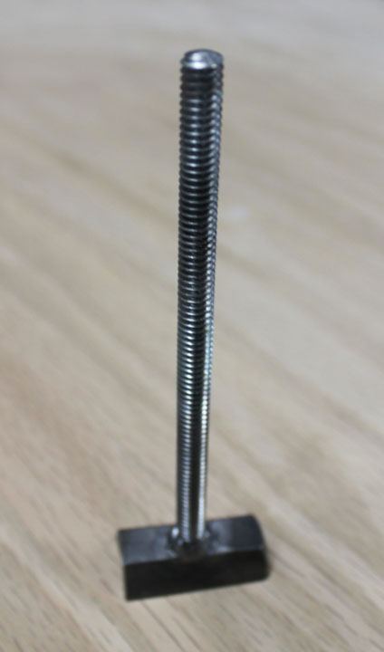
Fig. 8 The plans call for the quick release mechanism to use a split nut, joined with a threaded rod by epoxying the pieces into a block of wood. The bottom is the nut cut in half with threads that engage or disengage the threaded rod to micro-position the carriage. Although cutting a piece of wood to house the coupler and filling it with epoxy is a solution that requires only simple tools, I decided to make it a bit differently. I have a good friend, John Groeneveld, who is a very capable aircraft welder with a nice TIG setup who welded the above part for me. Deciding to use a coupler instead of a nut for more thread contact surface, I split the coupler on the metal bandsaw but careful hacksawing will do the same. By chucking the threaded rod into a drill press and lowering the end onto the coupler half, the rod stayed perfectly aligned while John made a very nice weld. Lighting was somewhat limited when I took the photo in Figure 8, so sorry about the crummy depth of field.
Fig. 9 I finished making the gears (I used a CNC machine to cut them out of oak, making them a bit larger than the ones shown in the plans, but you can make them with a bandsaw or even a jig saw and sandpaper just as well.) Figure 9 shows the majority of the hardware - the 3/8 16 TPI inch threaded rod with the 8 tooth gear and bushings on both ends is shown on the left. In the middle is the quick release split coupler piece in Figure 8 with a spring, bushing, and knob added, and on the right is the upper crank assembly with the 16 tooth gear and bushing. The next step was to build the carriage. Dimensions revolve around the 24 inch drawer guides, which determines the maximum width of a board on which you can make the joint. 18 or 16 inch guides would produce a more compact unit, and you would change the carriage length dimensions accordingly. After adding the clamping fence T-Track (I got this from Grizzly, who has them pretty cheap and only requires 1/4-20 inch bolt heads.) I decided to go ahead and add the fence, which I am looking forward to using.
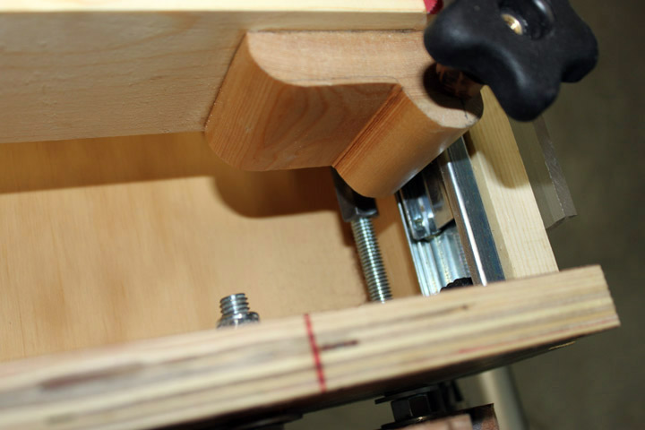
Fig. 10 I changed the part that holds the quick release rod a bit, waiting to drill its position until the base and sides were done to see how the guides went together and allowing me to see just where the quick release rod fell onto the position of the threaded drive rod. The fit of the quick release mechanism is critical. If the 1/4 inch threaded rod has any play to it at all, it directly affects the size of each finger in the joint. I am glad I used a coupler as its many threads makes a very positive engagement with the threaded rod, as well as using 1/4 ID bushings in the bracket to keep any movement of the threaded rod to a minimum. Also, choose the spring between the coupler and the bushing with care, as it represents the force that will keep the coupler on its proper position of the 1/2 threaded drive rod. Since no advice on what spring to use was given, I ended up getting a "box o' springs" from Lowe's for $6 that allowed me to try out various sizes. The red line on the top edge of the side is an index mark for the large gear. When not using a template, moving the carriage precisely involves counting the rotations of the gear. The threaded rod is 16 threads per inch, which means one revolution of the small gear moves the carriage 1/16 of an inch. Since the gear ratio is 2:1, one complete revolution of the gear crank moves the carriage 1/8 of an inch. The red line is used as an index mark to match up with a red tooth on the gear to make sure one complete revolution has occurred.
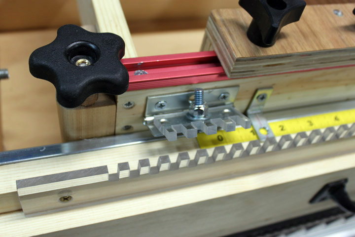
Fig. 11 This jig's first project was to cut the teeth for the template - you can see the jig works great just by looking at the regularity and fit of the template and its locking key. I used Lexan for the template material. BTW, Lexan (polycarbonate) is NOT Plexiglas (acrylic) - Plexiglas cracks if you just look at it funny, while Lexan takes a lot of abuse and is very tough. One build note - you need the hinge to stay put when you lift it, or gravity keeps trying to engage it into the template teeth while you are moving the carriage. To make this happen, before mounting it place the hinge in a vise and rap the hinge barrels sharply where they meet - this slight dent will not only make the hinge stay where you put it, but will take up any sidewise play in the hinge. Also, the end of the 1/4-20 screw sticking up from the template key provides just enough length to grab with your finger to raise and lower it onto the template. Also, I added a tape measure strip with a "hardware store" angle brace to form a cursor to be able to confirm the correct movement as the carriage is positioned. The clamping fence is a great idea - if you've already built a woodgears jig, just adding this idea to it would be a welcome improvement.
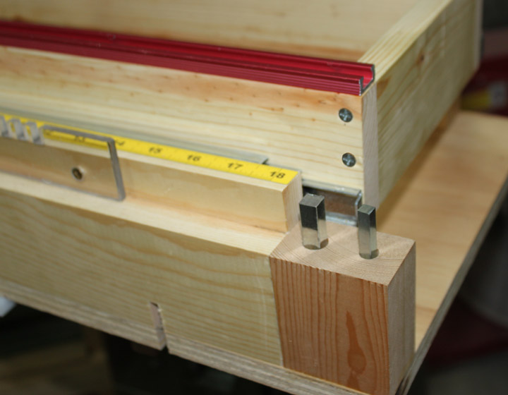
Fig. 12 Here's a simple but useful thing I added a little bit later - on the right of the jig base there was a bit of a ledge left that I filled in with a block of wood and drilled to hold two spacers. These spacers are precision made and are useful for setting things exactly 1/4 and 3/8 inch apart. If you go to a Fastenal or tractor supply store, they are sold as "square keystock" and are machined to tight tolerances (mine indeed measured .250 and .375) but only cost a few bucks for a one foot length. I put these near my router table and table saw as well. Were I to do it over... If I were to build the Woodgears jig again, I would have made the carriage wider to better allow for the use of a fence like Stumpy provided. I would also come up with some non-slip bearing block for the drive rod bearing, and I would be pretty tempted to use drawer guides as well, even though that adds to the cost of the jig. For the Stumpy jig, I already did do some things different from the plans, as noted above. If I were to do Stumpy's jig over, I think I would have tried to find a stainless steel threaded rod for the main drive. It's over 26 inches long, supported at each end, and the "mystery" alloy they use for hardware store allthread (I suspect it's just a random mix of whatever recycled metal that can be picked up with a magnet) sags a bit in the middle, especially since the QR spring is always pushing down on it. It only has to sag the depth of a thread groove to start skipping threads when turning the gears and thereby ruin the piece. I can't report that it has actually been a problem - it hasn't caused me to waste material or anything - but I suspect that a stainless rod would be less prone to sagging and it really shouldn't affect the cost by much. The bottom line is I really enjoyed building both jigs, and now I have a solution that means I won't hesitate to incorporate finger joints in one of my projects! Much thanks to both Matthias Wandel and Stumpy Nubs for their work. Stumpy has since come out with yet another box joint jig using a 16 pitch threaded rod as a positioner. That one appears to be much simpler to build, but IMHO not as easy to use. Like I said, the vast majority of joints I do are either 1/4 or 3/8, and I use a blade in the saw to match them. The templates for both of those are very rigid and pretty much fool proof. The only mistake possible is to cut the same pass more than once, which does nothing to the workpiece. Even though these are fun to build, I think I will pass on the new one - I know goodness when I see it, and the one above is quite good enough for me. |
|
|
Comments may be directed to gary at liming daught org. Thanks for looking! |


