|
|
| Home Page |
Fig. 1 This is a build page about how I made my FPV (first person video) goggles shown above. First of all, there are commercial versions of these that cost hundreds. Second of all, there are plenty of others who have done this - there are great examples and interesting thinking about them at the RC Groups forum here. This is just how I did mine based on the good information supplied there.
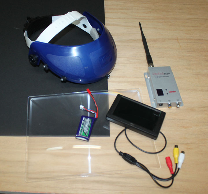
Fig. 2 Above are most of the components needed. Upper left is the black sheet of foam board - most are white, but if you get white you're going to have to paint or cover one side black anyway, why not get one already black? The blue and white head mount on top of it is a replacement assembly for a welding helmet like this one I got at a tractor supply store. I paid $12 for it, it's comfortable, adjustable, easily flips up out of the way, and is meant to carry some weight. Some folks like to glue the screen onto ski goggles, but they only have a single strap around the back of the head, so I am going with this arrangement. We'll see. To the right is the 900 mHz video receiver I already had from my quadcopter work which plugs into the screen. Its a bit old and large - perhaps I'll think of a way to attach it to the back of the headband. The screen I got here for $17. They are cheap because they were made for those rear-view cameras that go in cars nowadays. This one has a 16:9 (aka "widescreen") aspect ratio, but it is still only 420 TVL, so we'll see how it looks. Next is a 8.5x11 inch Fresnel lens like this one,which will provide a 3x magnification of the screen. I got mine on ebay for $7, so shop around. (BTW, Fresnel is a name, and is pronounced frey-NEL with the accent on the last syllable. The 's' is silent.) Last is a 380 mAh 3s (11.2v) LiPo battery. I hope that's big enough to last for a couple of hours with some spare, but like I said, we'll see.
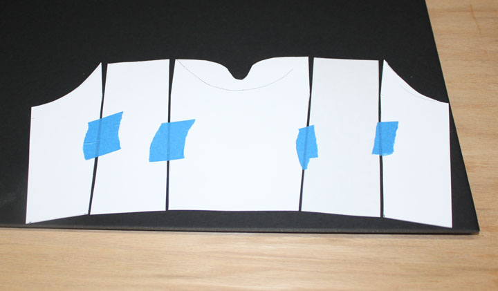
Fig. 3 The build starts by matching the screen to the theatre box. (The box that goes in front of your eyes to hold the screen in place is called the "theatre.") The outside dimensions of my screen is 120mm by 70mm. so that fixes the width of the theatre. The length is a matter of experimentation - hook up the screen to a video signal, and move the screen and the Fresnel lens towards and away from your eyes until you have a comfortable view. For me, that meant the lens was 30mm away from my eyes, and the screen was 160mm away. (I am a bit nearsighted without my glasses, so the Fresnel lens makes up for some of that, but your mileage may vary depending on if you use glasses, and/or if you need them while FPVing.) Now that I know the major dimensions, I cut the sides out of some cardboard to form a template. Taping them together allowed me to verify the size of the needed pieces and then cut outlines to fit my head. I then re-taped the cardboard pieces together, allowing for a 4mm gap for the corner bend radius of the foam board. I also cut the top of the box down the middle, which will be the only seam. I then traced the cut line for the theatre onto the foam board.
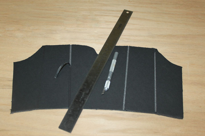
Fig. 4 Above is the foam board cut out, and I am removing the inside strip of cardboard to form a bend radius channel for the box. This allows the theatre to have only one seam, and it fits the screen and my head perfectly.
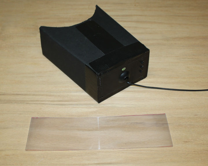
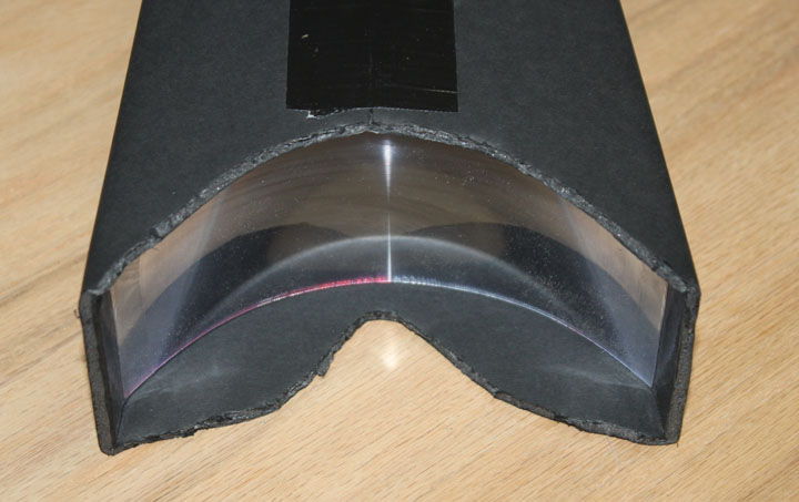
Fig. 5 Above I've folded and taped the box, and fitted the screen to the end of the theatre. Next is to cut the Fresnel lens to fit inside the theatre, just a bit over an inch from my nose, with a slight curve to it. Then, some soft foam around the face area to not only ensure comfort, but keep out any stray light. The inside of the theatre should be flat black, with no possibility of glare or reflection. I started by cutting the lens to the right height, and then cutting the width oversize, trimming it down until I got the right curvature when inside the theatre.
Fig. 6 The lens is trimmed and taped using some packing tape to form the curve. The center of the lens must be in the center of the theatre view. Also, the ridged side of the lens is facing away from the screen.
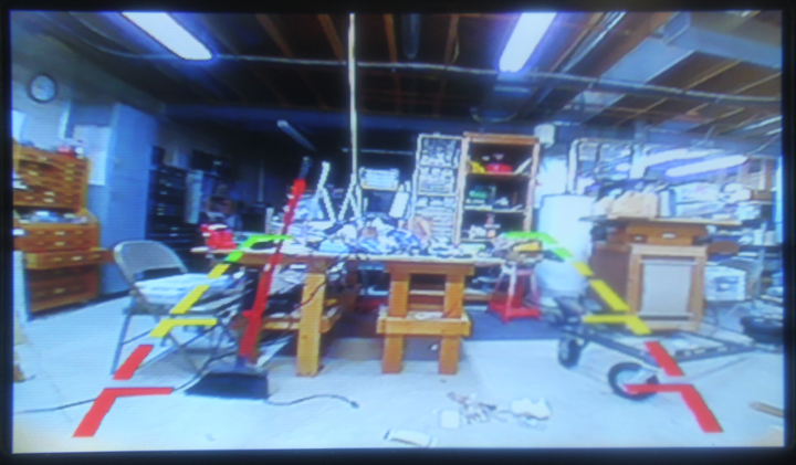
Fig. 7 The view inside the goggles - the lens is placed inside the theatre with a curve to it just enough to compensate for the 'bow tie" effect of being so close to the screen. As you can see, the resulting picture is rectangular. Note the camera used at the time of this photo was not set level to the horizon, and I didn't think to clean up the shop a bit more before taking the picture. Also, you can see this monitor comes equipped with "backup" lines - perhaps these will be useful in guiding the mower in straight lines. We'll see.
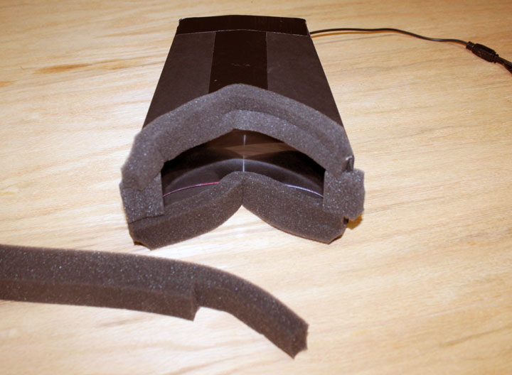
Fig. 8 Next is to attach some foam (not shown in Figure 2) around the edges to make it comfortable as well as seal off any stray light that could enter into the theatre. I cut the foam with scissors lengthwise to form 1/2 inch thick strips, then cut a shallow groove down the length of it to allow the edge of the board to be inserted and glued. The fit is great, and it weighs very little - I can see why some builders just velcro some elastic on the sides at this point. However, the problem is the LiPo, receiver, switch, and mass of wires all have to go somewhere.
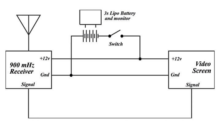
Fig. 9 Above is the simple schematic I have for the goggles. I was temped to cut off the bulky RCA connectors and solder them, but decided to sacrifice looks for ease of replacement. I've included a cheap ($3) battery monitor (also not shown in Figure 2) that is ready made to plug into the LiPo's balance port, so that the goggles will beep at me when the battery gets too low, as well as tell me power is ok when I turn on the switch.
Fig. 9 Comments may be directed to gary at liming daught org. Thanks for viewing this build log! |