| Welcome to a...
Build Log |
|
Fig. 1 There have been several DIY remote controlled (R/C) lawnmower projects that have videos posted or information about them online; this is yet another one of those projects. My intent is to mow the lawn using a standard R/C transmitter, at least initially, and have on board cameras that transmit views of the mower's position back to the operator for feedback control. What may be a bit different on this build is the use of FPV (see below) equipment to control it. I plan to do this project in three phases:
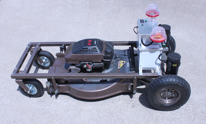
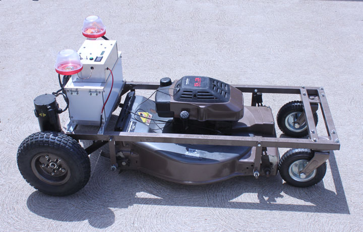
This project may also have the wrong name - once R/C mowing is working, I might also look into coming up with some kind of attachments for fertilizer broadcasting, a snow blower front end, and a wheelbarrow dumper. Figure 1 above shows the completed Phase 1 mower, and I hope to post a movie of it mowing the lawn under remote control. Today, transmitting a video signal back to an operator to accomplish remote control is often referred to as First Person Video, or FPV. It's the same thing they do with R/C quadcopters, military drones, and even some surgical machines. For me, this might be a first step toward the development of a more automatic lawn mower. Some of its advantages are that it removes me from the hazards of heat, dust, mold, rocks, etc. that can come flying out the of the mower. In the past, this kind of thing has been called teleoperation, since it not only allows remote control but provides remote sensory information (video in this case) about how the local operation is progressing. The idea is actually somewhat old - believe it or not, the first patent issued for remote control of a vehicle using "wireless" (RF) technology was to Nikola Tesla in 1898 (Pat. No. 613809) and that year he demonstrated the technology as a remote controlled submergible boat to the U.S. Navy! However, he did not have the digital cameras, displays, and video transmission devices available for doing FPV. I will be using standard transmitters for the video, so I could use any set of 900MHz goggles that are available for this purpose. However, I will be building my own. Because these are applicable to other projects as well, I documented making those on a different page, given in the menu on the top left column. Also, I made a transmitter tray for the transmitter, also on that menu. Before going any further, please read the following: many people understandably associate R/C technology with toys, but this project is not a toy or a game. All lawn mowers are dangerous. According to the Consumer Products Safety Commission, over 234,000 people received emergency medical treatment for lawn mower related injuries in 2012. That's one of the reasons I am building this thing, but it is also a warning about the dangers of a project like this. I share this build log experience with you in an educational and experimental capacity only, and I make no express or implied claim that this project is safe to use. In fact, I am telling you that a project like this one is dangerous to you and those around it. Project safety is a primary concern for me, but I don't know anything about you or your situation. I don't know if you have an open or fenced in yard, or have unsupervised kids or pets running around, or if you have the skill and wisdom to reliably create and safely operate something like this, so there is no responsibility I can take for your project. Be advised that this project is potentially lethal to people, animals, or landscaping. If you decide to make something like this, you must know what you are doing and you must take full responsibility for your decisions, actions, manufacturing skill, testing, operational skill, design, and overall project safety for everyone concerned. I will not accept any responsibility for what you do with the information provided here.
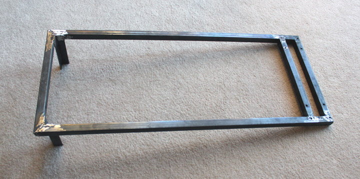
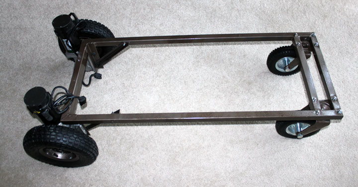
Fig. 2 OK, having said that, on with the log. I started with a basic frame, shown above. This was made from 3/16 wall 1 1/4 square chromium/molybdenum steel tubing, miter cut on my metal bandsaw and welded up. It turned out to be not too heavy - it's about 6 pounds - but it is very strong. In the rear (to the left in the above photo) were two pieces of 1/8 inch "angle iron" welded well into the corners to provide a mounting fixture for the motors. The dimensions of the frame were chosen to just fit over the main mowing deck of the mower I plan on using, but leave enough of the mower on its sides to get a close cut on the grass. On mine, the outside dimensions are 19.5 x 48 inches. Everything else that needs to attach, like the battery frames and the electronics will bolt on. I've tried to keep the center of gravity (CG) as close to the ground as possible. Holes were then drilled to fit the front pneumatic tire casters, and it's ready to get a primer coat and paint.
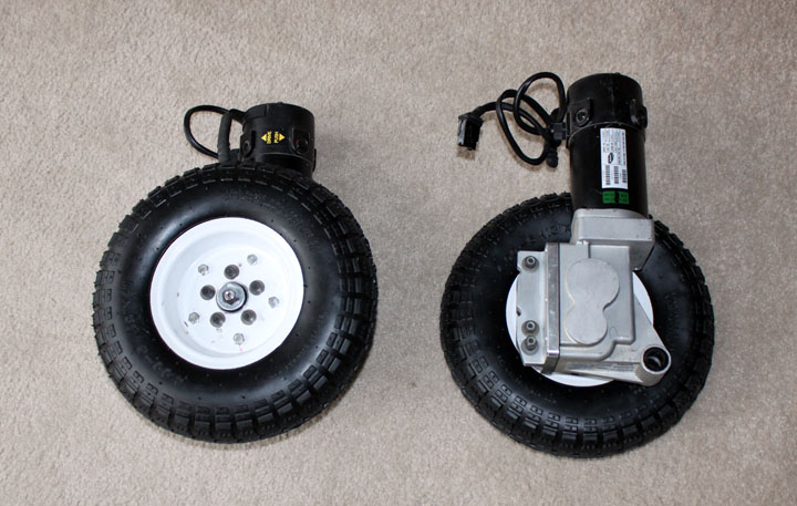
Fig. 3 I bought a set of electric wheel chair motors off ebay, which are very powerful and quite heavy. I popped the bearings off the 13 inch pneumatic rear wheels and cut off the protruding bearing housing on both sides of the two-part wheels so that they would lay flat on the wheel drive hub. I then drilled out the hub's 5-bolt pattern on the wheels and mounted them on. I have a yard with some steep hills. In fact, at a different house I used to use a riding lawn mower, and would use it at my present property except that some of it is too steep for one. I am not sure if these thin tread 13x4.00-6 tires will have enough traction for either the grassy hills or snow, but we have to start somewhere. These use an inner tube, which I think is a probably good thing in this application. For $13, the price is right. Because I have steep grades to deal with, I need to have some kind of fail-safe for the wheels, so that the mower does not runaway down a hill should the power get cut off, it runs out of RF range, or I just turn it off. Luckily, these wheels have a nice electric brake on them that are normally engaged. In order for the wheels to turn, 24 volts must be applied to each brake. (I have seen some builders removed these brakes entirely rather than have to energize them, but if the transimiter fails or gets out of range, on a hill, you might have a mowing mower rolling downhill on it own!)
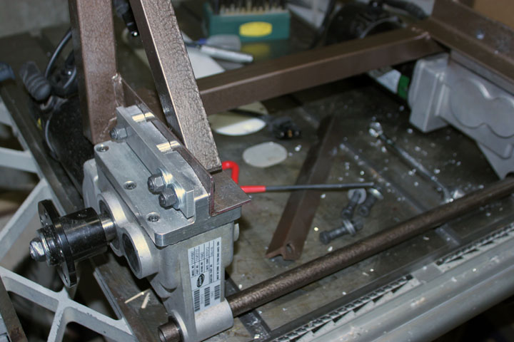
Fig. 4 Here is a close-up of the motor mounts being attached to the frame (after it was painted) with 3 bolts each. The 45 degree brace of painted angle iron was bolted on to relieve some of the stress on the corner weld, and a 3/4 inch stabilizer of steel tubing was inserted into the bottom of both of the motor gearbox frames. A simple cotter pin on each end holds it in place. Later on, I wanted more clearance around the mower, so I trimmed the 45 braces to be mounted with the flange away from the center, instead of toward the center as is shown above.
Fig. 5 Here is the painted frame with all four wheel assemblies and motors attached. The plan is for the mower to simply be suspended from the frame and I will use the mower's height adjusters to set the mowing height. If these motors can handle moving people up a ramp in a wheelchair, they should be plenty of oomph for a lawn mower.
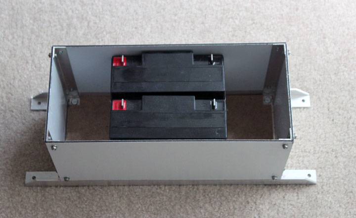
Fig. 6 Here I've constructed the battery box out of some aluminum angle as well as some leftover sheet material I had from another project called Dibond - it's 2 aluminum sheets with a polyethylene core, about 3/16 inch thick. I made the box larger than needed to be able to accommodate several different sized batteries (it will hold 4 of the above Sigmatek 18 amp hour 12 volt SLA batteries) in case I need to increase capacity. It has a hardboard bottom, and from the same material I will make a hinged and latched lid for the box.
Fig. 7 Above is the preliminary schematic I have for Phase 1 and Phase 2. I have made many decisions here - already, all six channels of the transmitter/receiver are used. One for each motor, one for the arming relay to enable/disable the throttle, brakes, and beacon, one for a camera selector, and two for the pan and tilt of the top camera. My transmitter only has six channels, so that fills it up - if I need an extra channel, I may be able to do without the tilt axis of the top camera. At this point I will be using three cameras - one fixed one looking forward over the left hand mow line, one fixed one looking aft, and one mounted higher up on the frame that can be panned and tilted around. The selected camera's video signal is transmitted back to a remote receiver that I will be monitoring using some FPV goggles for operation of the mower. Most mowers have a "deadman" switch on them - in order to operate the engine, you have to grip something on the handlebar to enable the throttle. If you let go of it, the throttle closes and the engine automatically stops. This is a good idea, as it's an important safety issue to prevent a running mower taking off for parts unknown if something goes awry. Although it may not be obvious, there are 2 important safety features here. The first one is the arming channel on the R/C transmitter that turns on an arming relay, which routes power to the rotating beacon, energizes (releases) the wheel brakes, and moves the throttle servo. The throttle servo works like the "deadman" switch in that it opens or closes the mower throttle which allows me to kill the mower engine and stop forward motion instantly by just throwing the gear switch on the transmitter. Also, the R/C receiver I am using (the OrangeRx R920X V2) is the type that if it looses signal (as in the mower getting out of range of the transmitter) all servos will go back to the position that they were when the transmitter was bound to the receiver, which means the arming relay will close, turning on the brakes, stopping the motors, and killing the mower engine as well. To increase the R/C reception, the receiver incorporates a satellite receiver add-on that helps with diversity reception, which I hope will be helpful for getting through trees and around the corners of buildings. Since I am also thinking that this might be used with a snowblower front end, I am really hoping I can maintain radio control while remaining inside the house! The controller is a Sabretooth dual 25 amp controller made for this purpose. It is regenerative in that when the motors slow or stop, the power in the coils are fed back to the batteries, helping to keep them charged. It also provides either direct control from an R/C receiver (like in Phase 1) or can talk to a SBC (single board computer like an Arduino) for Phase 3. The receiver will be wired as follows: the forward/reverse motor control to the elevator (channel 1), the left/right motor control to the aileron (channel 2), camera pan control to the rudder (channel 3), camera tilt to the throttle (channel 4), camera select control to the flaps switch (channel 6), and the arming servo to the gear switch (channel 5). The transmitter is a mode 2 transmitter so that the motion control is the right joystick and the camera control will be on the left joystick. The batteries are wired through a switch to operate either in series (24v) in operation, or parallel (12v) while charging. This allows me to use a cheaper 12v charger that is appropriate for SLA batteries. There are also a couple of voltage converters to provide 12 volts for the beacon, and 5 volts for the camera, video transmitter, and servos.
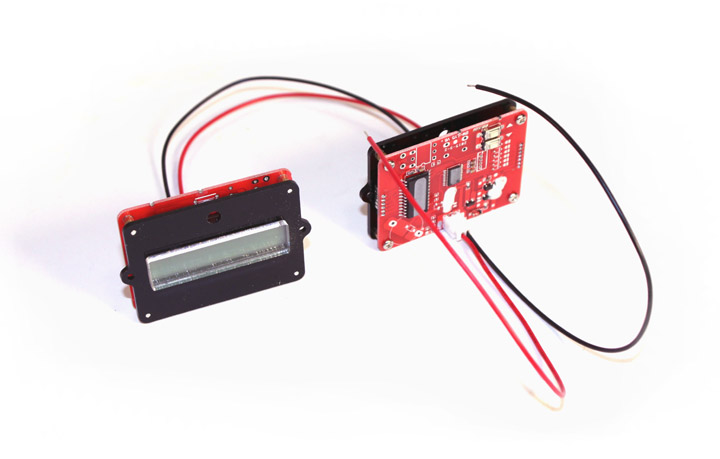
Fig. 8 I decided to add a 12v battery monitor circuit, shown above, which I got on ebay for $6. These are kind of neat because you program them with two pushbuttons on the back to be set for SLA or lithium batteries, and also specify the nominal voltage. In the window is displayed a battery with its charge state, and a 2 digit percent full number. Rather than have it on all the time, draining the battery, I will just add a push-to-test momentary switch so I can turn them on while in the off/charge position of the power switch. They only take about 7 ma each to operate. Perhaps in a future phase I will add a circuit to monitor the battery condition via an on board computer to check its condition remotely. In addition, I added a seven segment run time panel voltmeter to show total battery voltage while the mower is running.
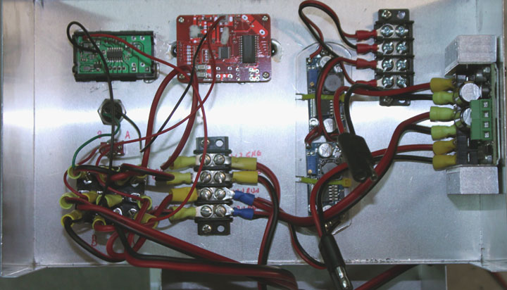
Fig. 9 Here I've mounted the major components on the schematic in a 10x6x3.5 inch aluminum project box, which I mounted atop the battery box lid. I chose aluminum because I wanted to to use it as part of the heatsink and in turn have it mounted to the frame as well. The motor controller, shown on the right, can get hot in operation, so I will probably put a fan on it as well, but a fan in a mowing environment will probably need a filter in front of it. I will just mount it on the side of the box for now and see how warm it gets in operation. Upper left is the run-time voltmeter, and next to it is the red battery monitor of Figure 8. On the lower left is the 4PDT switch that takes power from the batteries and routes it to either the charging circuit at 12 volts, or to the run circuit at 24 volts. On top is the voltmeter and charge status display, with a battery select and push-to-test switch to operate them. In the middle are the 12 volt and 5 volt regulators, mounted on a scrap piece of Lexan as an insulator. What's left is to mount the receiver and the camera select switch, but they should not be in a metal enclosure, and run the wires from the motors and beacon. I decided to use crimp terminals and barrier strips instead of just soldering everything because they provide a easy way to change things later on if needed, although it did add about $6 to the cost of the project. The barrier strip on the bottom has the 12v charger/24V run distributions, and the barrier strip on the top receives the regulated 12v and 5v distributions. I also added plugs for the motor wires to be able to disconnect them easily to remove the box. All that is left for the Phase one wiring is the receiver, which needs to be outside of the metal box. This box design evolved over time, so I would probably lay out the displays and switches differently had I to do it over again.
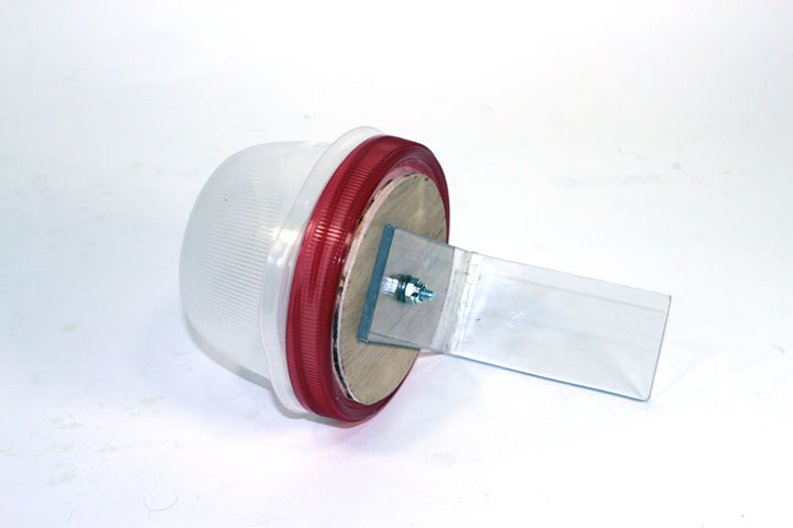
Fig. 10 I wanted to house the receiver as well as its remote satellite in some kind of protective enclosures, but one that wouldn't degrade the radio reception. I made two of the above. It consists of a small lidded food storage container with a thin plywood base to give some support to the lid, and a strip of Lexan bent to 90 degrees in a vice. They will be attached on both sides of the control box.
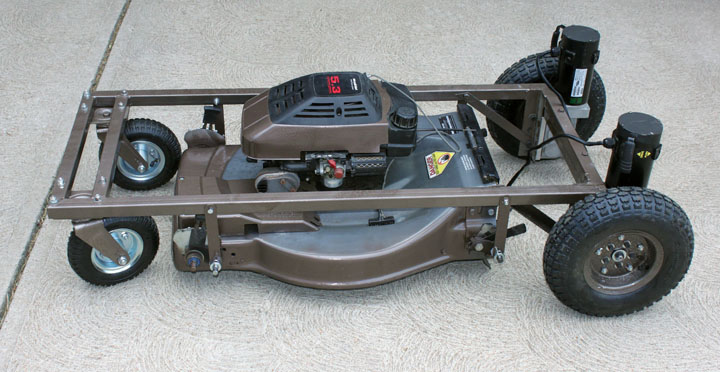
Fig. 11 Here the donor mower has been cleaned up and touched up a bit on the paint, and is suspended from the frame. The mower is hung with some bar between the frame and the wheel axles, and the height adjusters are set to the height I am used to for my lawn. I was really tempted to put the batteries down behind the mower to keep the CG as low as possible, but since this mower is a rear exit mower, I wanted to keep the area behind the mower somewhat clear. As it is, the CG is pretty low already. If the mower clogs in heavy spring grass, I may also need to fashion a sheet metal shroud to hold the back door open at an angle while keeping the cut grass directed downward. Since I have steep hills to deal with, I will also see about the need for any cross bracing that may need to be added later in order to keep the mower rigid to the frame.
Fig. 12 Here the control box (shown in Figure 9) is attached to the lid (not previously shown) of the battery box (shown in Figure 6) along with the two antenna mounts (shown in Figure 10) and this assembly is bolted to the frame. The motors are plugged in and their polarity verified - if they turn backwards from what is expected, you just reverse the motor leads. Now all that is needed is the R/C controlled relay for the arming switch, and Phase 1 is ready to rock and roll!
Fig. 13 Comments may be directed to gary at liming daught org. Thanks for viewing this build log! |
|