|
|
||||||
|
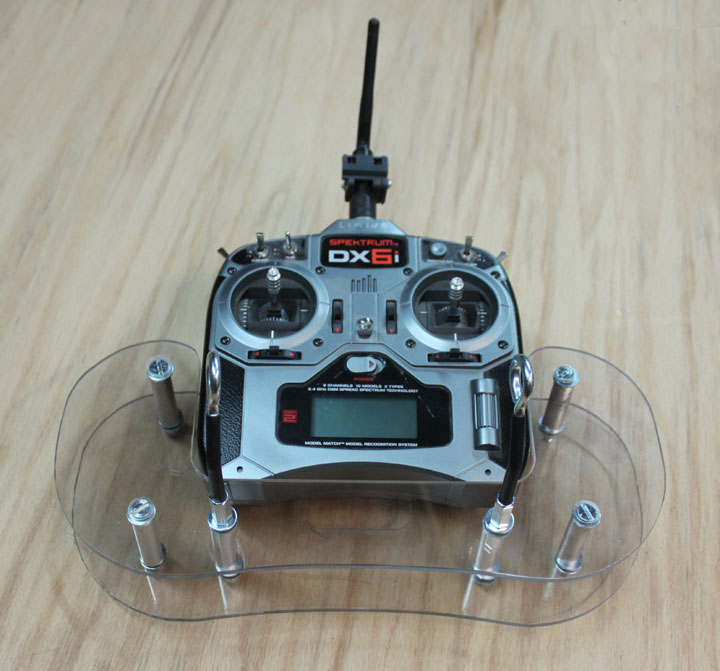
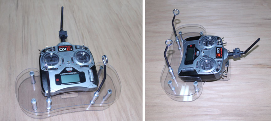
Fig. 1 This is a build page about how I made my R/C transmitter tray, shown above. There are commercial versions of these that you can buy, and there are several DIY versions described on some of the R/C forums. They are fairly simple devices, and many get by with just using a neck strap connected straight to the transmitter, but I definitely need to use one of these. In my case, I have neck vertebrae issues that don't allow much load bearing any more, and I cannot look up for very long, so just hanging the transmitter with a neck strap does not work for me. I need to support the weight of both the transmitter and my hands on the controls from my shoulders, not the neck. So, after sifting through some of the R./C forums for xmitter tray ideas, I came up with the following.
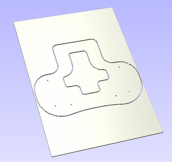
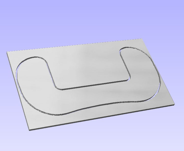
After looking around, I saw several trays that looked about right in terms of fit and function, so I made up a .dxf drawing to fit my DX6xi transmitter, shown in Figure 2, converted it into a toolpath for my CNC machine, and cut the base piece out of some 3/16 inch clear Lexan. Since I already had the Lexan, this is going to be lots cheaper than buying one. I am sure this would not work using acrylic as the bolts that hold the unit together would crack the acrylic. I also drew up the upper hand rest as a partial duplicate of the bottom piece, shown in Figure 3, and cut that out as well of the same material. If you don't have access to a CNC machine, you can print the dxf file in full scale (it's in millimeters) and paste the paper temporarily onto the plastic's protective film. Use a bandsaw or jigsaw to cut out the pieces, and then use a center punch to mark the hole locations, and remove the film along with the template.
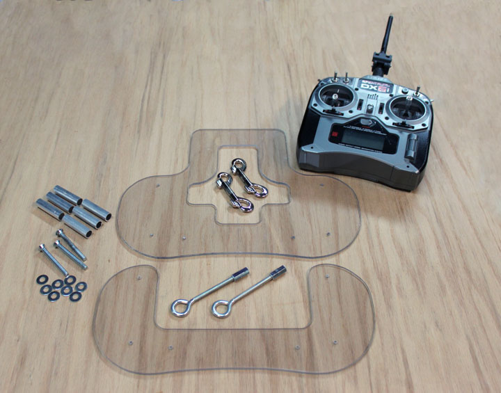
Fig. 4 Above are the major parts of the tray. The two clear Lexan pieces have their holes positioned by the CNC, and will be drilled out to 1/4 inch for the bolts. All of the nuts, washers, and bolts used are for 1/4-20 threads. The six 1/2 inch diameter aluminum tubes (2 inches long) are used to separate the base from the handrest. The 2 1/2 inch flat head bolts (there are only 3 in the picture, should be 4) are used to assemble the base to the handrest. The bottom two holes have eye bolts on top going through a couplers to some threaded rod for the bottom. I couldn't find 1/4 inch eye bolts long enough for the whole job, so I am using the couplers shown above already threaded onto the end of the bolts - longer ones were much thicker and heavier, and I want to keep the weight down. In the center above are the snap rings that will connect the eye bolts to the harness.
Here, the eye bolts were bent outward to a 30 degree angle, and some shrinkwrap put over the threads to avoid roughness around my thumbs. They were then threaded halfway into the coupler, and a length of threaded rod was cut, inserted through some washers with one of the aluminum tubes between the base and the handrest. The four outside holes on the handrest were countersunk for the flathead bolts, and their tubed columns have three washers used for each bolt. A clip, fashioned from bending some 1/16 inch aluminum around a bolt the size of the transmitter handle, was attached the front of the tray base to hold the transmitter handle in place. The harness clips onto the eyebolts. Attention to weight paid off. The weight of what is shown above is 3.18 lbs with the transmitter, and 1.50 lbs without it. Just placing my hands on the sides and either thumbing or pinching the sticks is a lot more controlled and relaxed. Perhaps it needs a cup holder, too!
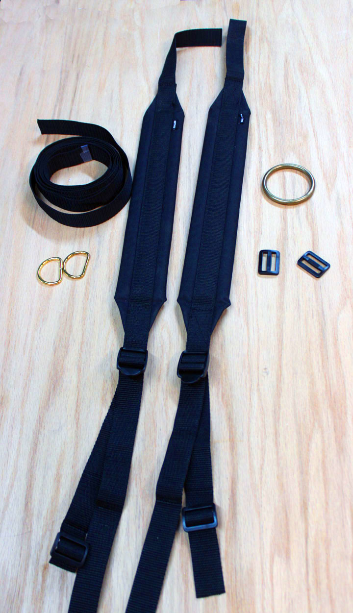
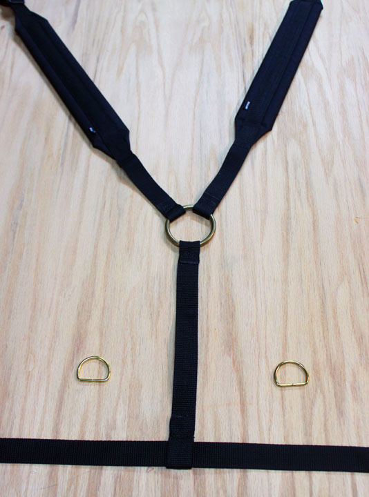
As I said, I need to suspend the weight of the tray and transmitter from my shoulders instead of my neck, so I need to make a harness to suspend the tray. In Figure 6 are the materials I used to make the harness - first I went to Walmart and bought two cheap rifle sling straps for just under $5 each. They are pieces of wrapped foam with one inch wide nylon strap sewn into them and should keep the straps from digging into my shoulders. They will be sewn to the brass ring in the back, and some of the other strap, shown on the left in a coil of 2 yards from Hobby Lobby at $1.49 per yard, will also be sewn onto the brass ring and come around to the front with the brass D rings which allow the snap rings to attach the tray to the harness. The slides on the right came with the slings, and I got the brass pieces from a friend who does leatherwork. So, the stuff above set me back about $15. To sew the straps, I used two leatherworking needles with some waxed linen thread using a saddle stitch, and all the cut edges of the nylon were melted to prevent fraying. Figure 7 shows the back of the harness, with a 14 inch strap sewn onto the ring that hangs down to form a loop on the end through which the "belt" part passes. This represents the bulk of the work.
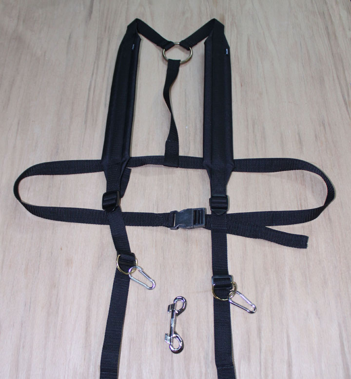
Fig. 9 Here is the completed harness. I found some cheap small carabiners (shown on the D rings above) to use instead of the snaphook (shown in the middle) because they were much lighter. Comments may be directed to gary at liming daught org. Thanks for viewing this build log! |
|||||||