|
-------- |
||||||||||||||||||||||||||||||||||||||||||
|
|
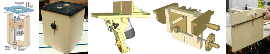
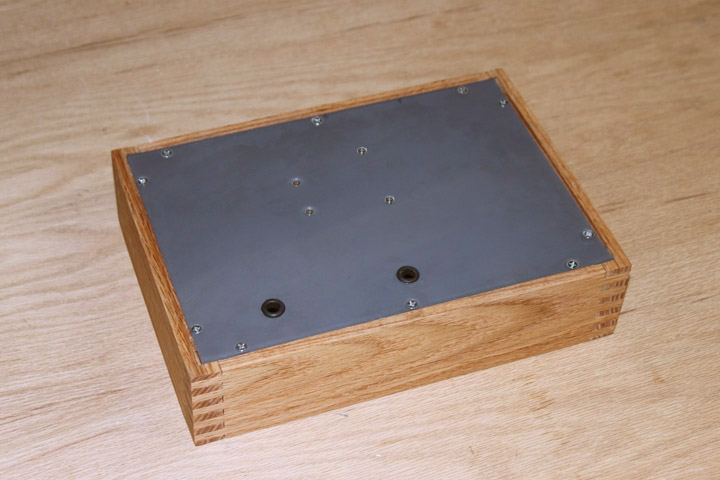
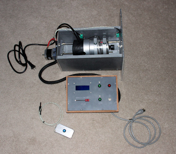 Fig. 1 Winter, 2016/2017 - I wanted a router lift for my router table. Above is what I ended up with, but it was an interesting road to get there. This web page is a narrative of that particular rabbit hole.
Fig. 2 As usual for starting a project like this, I spent a fair amount of time looking at the huge amount of stuff about routers on the web. Commercial router lifts are very expensive, and I wanted to knock something out in a timely fashion, so I narrowed the field to some DIY plans. The ones I looked at are (above left to right) the Shopnotes lift (issue No. 121 of Shopnotes, now Woodsmith), which I studied. I also bought and studied Stumpy Nub's lift plans, bought and studied Mattias Wandel's (Woodgears) plans, and bought and studied plans for John Heisz's lift. I also studied and thought a lot about Jay Bates' lift, on the right. At this point, I want to say that I both enjoy and respect the work that all these guys do. Each one of these devices have pros and cons, just like any device, and you may have a different idea than they did about what is good or bad in a router lift. Here is my thinking based on what I perceive my ideal router lift to be: I want to be able to raise or lower the bit with the workpiece in place on the table that might cover up the height adjustment hole, and the top-adjustment idea means using yet-another-tool to keep with the router. That eliminated the Shopnotes and Stumpy design, as well as most of the commercial ones. I should point out that this arrangement has worked fine for many woodworkers, it's just something I'd prefer to avoid. I also want to mention that Jay's design is stunning in it's simple construction, but as you will see, easy-to-build was not so much a factor for me in this case, but ease of use was.
Fig. 3 That left John's and Mattias' designs. I went so far as to begin to build both John's (above, left) and Mattias's design (above, right), but learned couple of things from them. Some of these designs (Stumpy's, John's, and Mattias's) acknowledge the slop in the wooden linear slide method that they used by needing a locking knob to loosen while changing height, and tightening to hold the router carriage firmly in place while cutting. The problem with locking knobs is that it always seems that the height changes a bit when it locks, and the knob is usually inconveniently located, like under the table. John's design allows the locking control to be out front where it should be, and the knob doesn't have to move with the height adjustment like Stumpy's or Mattias's does. While I am sure that it works fine for him, I just could not get on with John's wood-on-wood-plus-Vaseline slide idea, even after trying some Teflon tape or HDPE on the slides. Mattias's design is clever, as usual, but I've realized that I don't need the complication of the tilt (which makes the height adjustment and locking knob locations awkward) as I plan to let the table provide that function. I really want to avoid any design that requires me to get under the table to make adjustments, change bits, or lock the router in place. I have experience with linear motion from building both a CNC table and a 3D printer from scratch, and they certainly exhibit precision movement without the need to lock an axis of movement in place while cutting or extruding. Thanks to the popularity of those machines, the linear motion devices they use are much more available and affordable now. Also, using a motor under the table to raise and lower the bit means I can easily place the controls to a more ergonomic location. Once I realized that is what I wanted, sure enough I found commercial units that do this, but they start at $500 and go way, way up from there. Well, I tried my best to do something with one of those off-the-shelf designs, but I guess I'll just have to design Yet-Another-Lift. I can almost hear some readers saying something like "Isn't this overkill?" or "Hey, this is woodworking - who needs that kind of precision?" Well, the argument that wood swells and shrinks does make the need for precision less demanding, but getting a good fit still means getting pretty darn close. However, the biggest reason for the precision is that my range of materials has grown over the years. I find being able to make things not only from wood, but from HDPE, polycarbonate, acrylic, PVC, aluminum, etc. is a real advantage for many projects, and their properties often allow for, or even demand, a much better strength, fit, and finish. Those materials are way more stable than wood and they sometimes demand more precision. I don't mean to take anything away from the great beauty and satisfaction of woodworking that I really enjoy - it's just that I've expanded my range of materials. However, just because we will be using a computer and motors, etc. doesn't mean we need to have a complicated design. The goal here is to have a very simple user interface, minimizing or eliminating the need to remember anything complicated and using a minimal number of switches. I hope to have a design that will result in a lift that you can learn to use in under one minute. If this is going to be a motorized design, I can either use a DC gearmotor or a stepper motor to move the router up and down. With the gearmotor, I would need to use a height gauge, like this one to measure bit elevation, or I could use a stepper for movement and keep track of the steps to indicate the height as a bonus. If you are buying new off-the-shelf motors, DC gearmotors are pretty pricey and steppers have gotten lots cheaper. Using a DC gearmotor usually means buying surplus, and even then the resulting cost is about the same as that of a stepper. The problem with surplus motors is that their availability is hit or miss, so I think I'll go the stepper route. Since the stepper needs control and the Arduino is so cheap and available, I'll be using one of those, and therefore the natural portmanteau for this project is the ArduLift. This build has two parts - part one is the lift mechanism that provides carriage for the router, and part two provides for the electronic control of the stepper that moves the motor. If you already have a lift for your router, part two may be adapted to any lift where a stepper can be fitted to move the lift. Part One
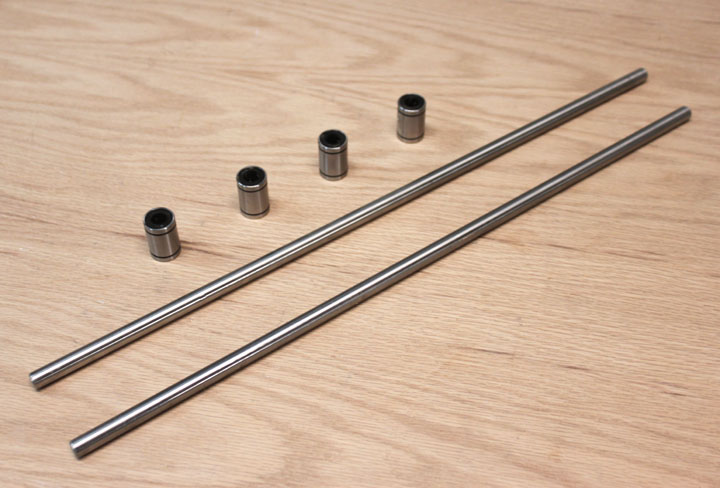
Fig. 4 Not locking the router in position means two things - using linear rails that are rigid on all axes but one, and using a drive mechanism on the remaining axis that has no play in it. There are several styles of linear rails available, some of which are more rigid (and more expensive) than others. One thing I learned from my CNC router table is that there really should not be any significant force from the cutter - if there is, something is wrong, like the feed rate is too high, or the depth of cut is too great, or the wrong bit is being used. The cutter should be doing all the work. I've never had to use more than just a few pounds of force to slide a piece of material into a spinning router bit at 10,000 rpm. The only force at play along the axis of vertical linear motion is when the router wants to twist around its cutting axis due to too much cutting edge resistance, or when the motor starts up, but again that is only a couple of foot-pounds at maximum. I think that a 10mm linear hardened tool steel shaft with corresponding linear bearings, shown above, should be sufficient to handle that without significant movement. If not, I can always substitute a thicker rod or use a different linear slide altogether, but I think this will be a good starting point. Also, they are fairly inexpensive, especially if you can tolerate waiting a week or two for them to come from Shenzhen. If you want them sooner, you can pay a few bucks more to get them from a US-based Ebay supplier like I did. I paid about as much for the rods and bearings shown above as you would for a good set of plain ole drawer slides - $18 including the shipping. The rods were cut to a length of 350mm, or 13 13/16 inches. This dimension dictates the size of many other parts, and determines the total vertical distance of the lift, which is right at 7 inches. You can shorten or lengthen this number as needed if a different travel is needed. A word about units. I am comfortable using both imperial and metric units, and I hope you are too. In the Midwest of the United States, materials and fasteners are either much cheaper or solely available in imperial units, so I make use of what's available. I also recognize the ease of metric in doing any kind of layout work, so I use metric as well.
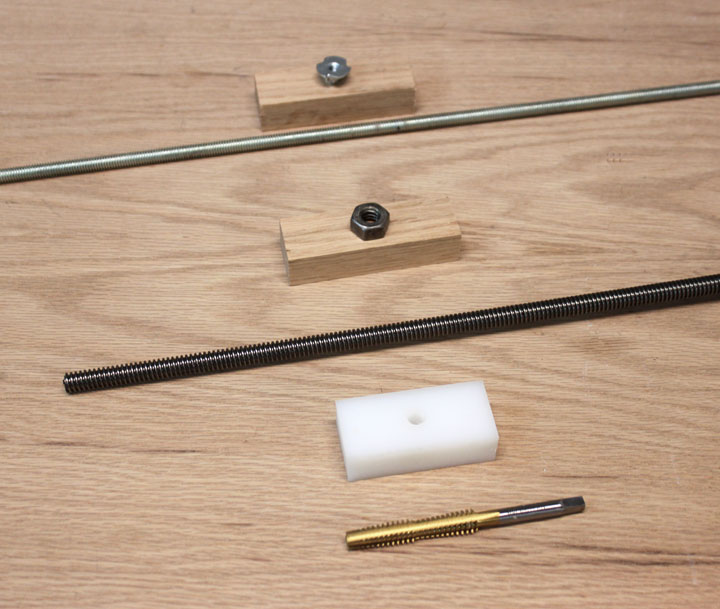
Fig. 5 Besides the linear slide, we need a way to cause the carriage to move, and this is often done in CNC type machines with one of several types of a motorized screw. With this approach, the carriage has a "nut" or threaded part to match the screw rod, so that as the motor turns the rod, the carriage is moved along its linear bearings. There are a couple of different ways to accomplish this, and three of them are shown above. The cheapest way is to use good 'ole threaded rod (allthread) from the hardware store, and attach a matching nut to the carriage somehow. This can be done by epoxying the nut in a pocket chiseled out to fit, or by using a tee nut (shown above at the top) that can be epoxied or held in place with small screws. However, both these parts are machined with a lot of tolerance, so the resulting fit usually has noticeable play in it, which is transmitted right to the router bit. Also, allthread is notoriously rough, so if you go that route I would at least recommend running the rod through a matching die to clean up the threads a bit. Another approach that has less play is to use Acme precision threaded rod and a matching Acme nut, shown above by the middle components. This means spending a few dollars more to have much less play in the movement. I found that the allthread route (a 18 inch length 3/8-16 rod plus a matching tee nut) had a cost around $2.00 at a big box store, and the Acme route (buying 3/8-12 Acme rod 24 inches long from McMaster-Carr for $15.25 and a matching 3/8-12 inch Acme nut from them for $2.35), had a cost difference of about $16 plus shipping. All of these approaches needs the nut to be embedded in hardwood or perhaps welded onto a mounting plate. However, I chose a third option, which also uses the 3/8-12 Acme rod, but required me to buy an Acme tap to match it. This tap, shown at the bottom of Figure 5, was $20 from Amazon. That allowed me to use a piece of 3/4 inch thick HDPE that I had on hand which I drilled and tapped. The HDPE is a great material for this as it wears very well, and at the low speeds and short movements used here, has a nylon-like self lubrication property. At first the threads cut by the tap were too tight, but running the tap through a few times allowed me to sneak up on a perfect fit with no noticeable play in it. Also, having this tap around will also allow me to solve future linear movement projects with little additional cost.
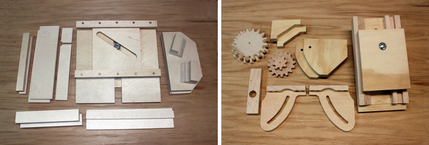
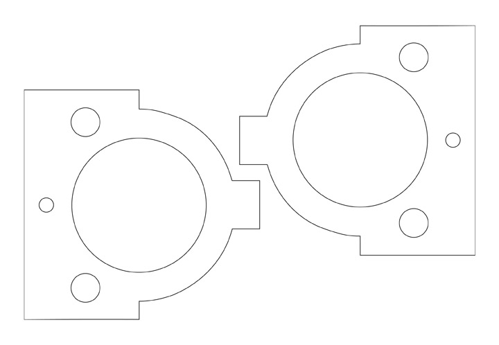
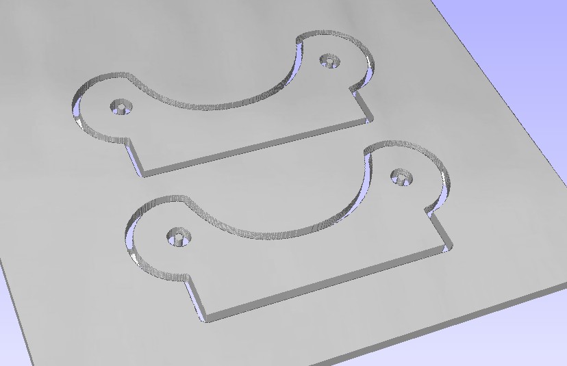
Fig. 6 Next I designed the router mount, starting with an approach similar to that used on some CNC router tables, utilizing the slide bearings shown in Figure 4. These two parts are intended to be cut from 3/4 inch Baltic birch plywood (BBP), and accommodates a "semi-standard" 3 1/2 inch router diameter. It also assumes 3/4 inch diameter rod bearings (which is what the 10 mm bearings were) and a 3/8 inch threaded drive rod. A slit will be cut on the tabbed ends to allow space for the rings to clamp against the router. A 1/4 inch hole will be drilled through the tabs to hold the bolt to tighten this clamping action. A DXF of this design is provided in the project file.
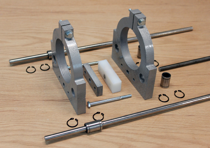
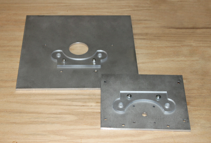
On the left are the parts for the router carriage. The router mount designs in Figure 6 were cut out on the CNC (although they could certainly be made with more conventional methods) and were given a coat of sanding sealer and painted with a hammered metallic silver. The white HDPE was tapped as described above and a 1/2 inch plywood spacer was added to space the clamps along the router body where I wanted them. The bolt holes were drilled through both mounts, the spacer, and the HDPE at the same time while the bearings were installed with the rods in place to get a nice tight fit. The external retaining clips (aka "snap rings", nominally 3/4 inch) are used to hold the rod bearings in place in the mounts. These clips are available out of a $5 assortment of them from Harbor Freight, or you can get 8 of them for about the same money from Fastenal, or you can get 50 of them from McMaster Carr for about $7.67 plus shipping. Such is the economics of scale. On the right shows how the parts were assembled to form the carriage with the router in place. Due to some lens distortion in the photo, the rods do not quite look parallel, but they are - the carriage moves up and down on the rods freely without the drive screw in place. If it does not move freely, something is wrong. When the threaded rod turns, the whole carriage rides up and down on the linear rails. The cost for the above is $18 (rods and bearings) + 15.25 (Acme rod) + 20 (tap) + 5 (rings) = $58.25. So, not counting the scrap plywood, everything you see in that photo, including the $40 router, was under $100. The router I used is the the cheap Harbor Freight product - I measured its runout, and it is surprisingly fairly good. From my perspective, it only lacks a locking mechanism for the collar which means it requires two wrenches to change the bit, but that seems a minor issue. Obviously, feel free to substitute your favorite make of router here.
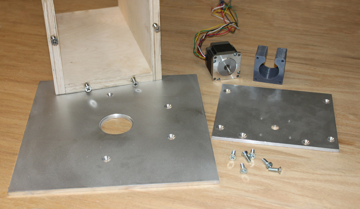
Fig. 9 The next assembly needs to provide three functions: provide a rigid frame to hold the rails, provide a firm mount for the stepper motor, and provide a way to mount the whole thing to your router table. This latter function may be dependent on your particular table. Some tables have the router (or its lift) attached to a mounting plate that is dropped into the top, and some use the table top as a cover that is lowered over a router mounted in the box. What I show you in this part is what I needed to do for my table which uses the drop-in mounting plate approach, but you may have to change this somewhat to adapt to the needs of your table. I started with a basic U-shaped frame also made of BBP. BBP has multiple thin layers, and will support threaded inserts in it edgewise. The inserts support 1/4-20 flathead screws that hold the bottom and top plates onto the frame, both of which were made from 1/4 inch 6061 aluminum.. The BBP sides and bottom of the frame are all 13 13/16 by 6 1/2 inches (350x65mm.) The two sides are attached to the frame base with 6 woodscrews. Note that the length of these three pieces must match the length of the linear rods, so that the rods have very little or no play in them when the carriage is placed in the frame. A word about using brass inserts - the way to mount these is to use a 1/4-20 bolt with a couple of jam nuts into the non-slotted end of the insert. Contrary to some I have spoken to, the slot cut into the insert is not for a screw driver to tighten the insert, but to help cut threads into the wood as it is installed. Therefore, the insert is installed slot-first into the wood. If this is your first use of these inserts, I recommend you search on YouTube for a tutorial on how these are used. Installing these into the edge of plywood risks splitting the plywood, and I am not sure this approach would work on cheaper plywood with fewer plys, but I might be wrong. I do know that the resulting fastener using BBP works great. I found it helped to use some beeswax (or soap, I suppose) as a lubricant when inserting these, and I held each holed edge in a wood vise while installing to support the walls of the plywood. Doing it this way made their installation go without problems - just insure that the bolt is kept perpendicular as you turn the wrench, like any tapping operation. (One observer, IAMSatisfied on HomemadeTools.net, suggested using cross dowels, like these instead of the threaded inserts. I have found the inserts to work well, but if they ever do fail, using the cross dowels would be a strong and easy fix.) The top plate is a 12 inch by 12 inch 6061 aluminum plate I bought on Amazon for $20. I drilled the plate with a 1/4 inch hole at dead center, and placed the carriage as shown in Figure 8 into the U-frame surrounded by 1/4 inch thick material to act as a spacer to provide 1/4 inch clearance between the carriage and the frame when the measurements were taken. With a plain 1/4 inch shaft then chucked into the router, I placed the top plate onto this shaft. This allowed me to position the top plate center over the center of the router collet, and mark the location of the walls on the bottom of the plate. From there, the holes for the mounting bolts in the top plate were located, drilled, and countersunk. The plate was placed back on the 1/4 inch shaft and the holes for the 1/4-20 brass inserts were located and match drilled with 1/4 inch holes, and then drilled out to 3/8 to accommodate the inserts. The bottom plate was marked to have its bolt holes centered on the 3/4 inch plywood edges, drilled, countersunk, and simply squared up on the U-frame where the insert holes were match drilled into the BBP edges. There was also a hole drilled for the Acme rod to pass through, as well as NEMA pattern holes for the 8-32 machine screws to mount the stepper and spacer into the bottom of the plate. Above shows the basic U-frame with the brass inserts installed, the top aluminum plate on the left, the bottom plate on the right, and the 1/4-20 3/4 inch flat head screws used to attach the plates. The top plate is 12 inches square, and the bottom plate is 8 x 6 1/2 inches. The center of the top plate has a lipped opening that was made by using a 2 1/4 inch hole cutter, cut to a depth of 1/8 inch into the material, followed by a 2 inch hole cutter that was drilled through. This formed a 1/8 x 1/8 inch lip for a plastic insert to be used to accommodate various diameter router bits. These inserts will be 3D printed using a customizable SCAD program that I wrote that is included with the project download file, as well as available at Thingiverse. The stepper needs to be mounted to the frame, and connect to the threaded drive rod via a coupler. To make room for the coupler, a spacer is needed. Rather than re-invent the wheel, I 3D printed the spacer shown above from a Thingiverse object, designed by Thingworld to fit a NEMA 23 pattern. (NEMA 23 simply means the steppers are square and are 2.3 inches on a side. However, this standard also calls for the outer mounting bolt pattern to be 1.854 inches between centers, and the center hole to be 1.5 inches. Again, you don't need a 3D printer to make one of these as it can be fashioned from wood using a drillpress. The spacer and stepper mounts with four 8-32 x 2.5 inch bolts and nylock nuts. Since there will be significant vibration from the router, all nuts on this assembly should be locking nuts, like nylocks, or use a threadlocker product. The coupler I used employed set screws to tighten, so I filed flats on both the threaded rod and the stepper shaft, and applied thread locker to keep the screws in place.
Since the linear rails are the same length as the frame, as soon as the end plates are screwed into the U-frame the rods can have no vertical movement, but they must be fixed at a specific location to make sure the router is centered over the hole and stays there. To accomplish this, I made two rail holders that are screwed onto the inside of the plates that hold the rod ends in position. I made them in the shape shown in Figure 10 and cut them out of 1/4 inch polycarbonate on my CNC, but they can easily be made by hand using a simpler shape. The critical dimension is that they must have 10 mm holes that are the same distance apart as those on the router mounts. Of course, the 8-32 flat head screws that hold them in place are countersunk on the top plate surface and use locking nuts. When mounting the end plates onto the frame, the linear rail ends must be captured into each of the pockets formed by these rail holders.
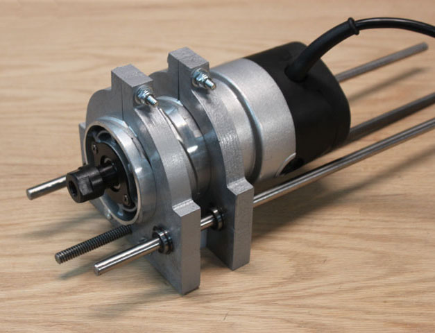
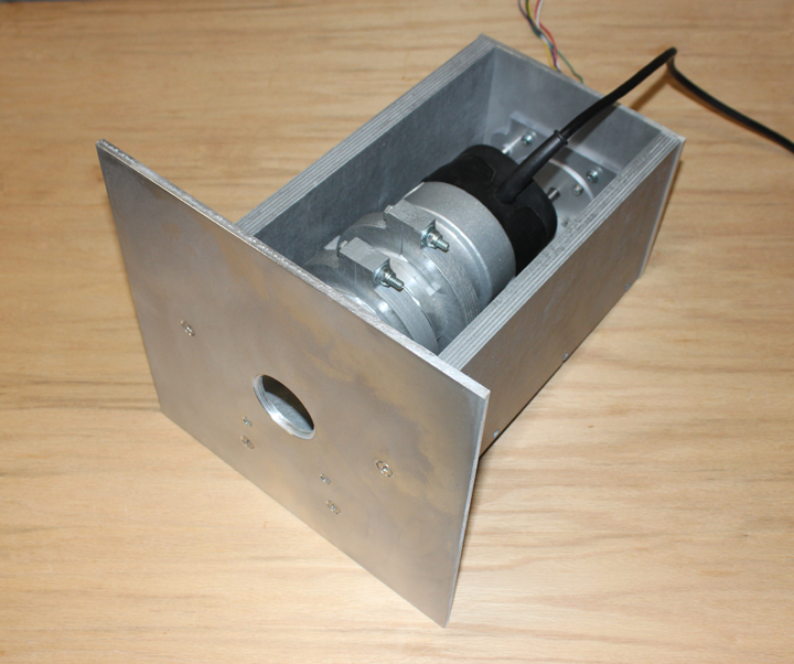
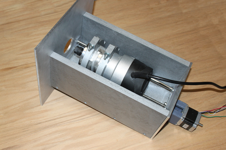
Above shows the assembled router lift, after sealing and spraying a hammered silver finish on the U-frame. The lift is ready to drop into a 12x12 opening in the router table. If you want a smaller plate to fit a smaller opening for your table, there is plenty of room to trim the 12x12 plate down in all dimensions. The router moves freely up and down the rails with little torque needed from the stepper. The upper end of router can travel right up to the bottom of the plate, providing much room to allow wrenches to get to the collet to make a bit change. The only remaining things to do are mount the limit switches and insert the probe sense wire into the router mounts, which we will do in Part Two as we hook up and test the control box. Part Two
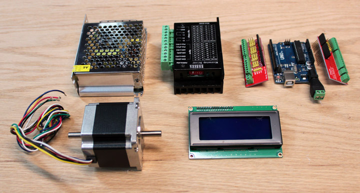
Fig. 14 The ArduLift electronic components. Upper left is a 12 volt 5 amp power supply (Ebay $7.49), top middle is the TB6600 stepper driver (Ebay $10.61) and top right is the Arduino Uno R3 (Ebay $7.17). Bottom left is the NEMA 23 stepper motor (MPJA $23.95 ) and bottom right is the 4x20 character LCD I2C serial display (Ebay $8.75). All the above prices includes shipping from US suppliers (you can get them even cheaper if you order from Shenzhen sellers, but I don't like to wait the two weeks) so the total for everything in the picture is $57.97. Those two red boards on either side of the Uno board are just plug-in headers that allow for wires to be connected to the Uno using screw terminals. I find them very convenient when experimenting because it allows me the ability to change the configuration with just a screw driver. They are not necessary for this project, but if you want to use them, add another $4 or so. Otherwise, you can use some jumpers with male header pins on them and cut off the other end to splice with wires to go to the switches. Once the unit is working correctly, I find it helps to use a bit of hot glue and/or electrician's tape on the header pin shells to keep them from working out. There will be significant vibration from the router, so securing all the wires in place is more than just a good idea for this build. In addition to the things shown above, you will need a toggle switch, three push-button switches, two 600 ohm resistors, two LEDs, and a 10K linear potentiometer. Everything you see above except the stepper is going into an enclosed box with a control panel for a cover. Since this device is only used for a few moments at a time, I don't plan on adding a fan or even much ventilation to the box. In fact, it the longest period during which the power will be on is while it is being demonstrated rather than while it is in practical use; it only needs to be turned on to position the bit - once the bit is in place the unit can be turned off.
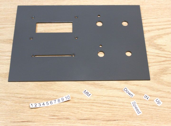
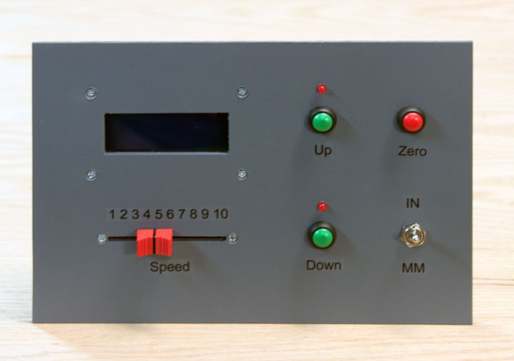
One the layout was decided, I cut the approximately 7 x 10 inch polycarbonate panel on my CNC and sprayed a coat of gray followed by a layer of clear coat. Once those dried thoroughly, I printed the labels, shown above left, on a sheet of clear laser printer labels and cut them out. They were then applied to the panel and several more coats of a matte clear coat went over them. I'll include the DXF for this panel with the software, but feel free to arrange the panel in any layout you like, and you certainly don't need a CNC to make one. Above right shows the panel populated with its components, ready to mount. The LCD display was mounted using four nylon spacers. These can simply be bought to fit, but I found some time ago that buying a length of nylon tubing, like that used to hook up a water line to a refrigerator ice maker, allows me to carefully cut with a utility knife as many spacers as I need at any length I need. I decided to use a slide potentiometer instead of a knob for the speed control, mostly because I am a bit tired of knobs, and my local electronics purveyor had them in stock at a low price. It would have been a bit easier (and take up less panel space) to just drill a hole and put in a standard 10K pot, but I like the look and feel of this a bit better. Regardless which style you use, make sure the pot has a linear taper to it, not the log or so-called "audio" taper. Originally, I had a toggle switch to just select coarse or fine movement, since it seemed to me that you only wanted it to move fast when going to the extremes, and then very slowly when you are zeroing or positioning it, but allowing a continuous range of lift speeds seemed just as simple and is a bit more versatile. Also, if you are going to want the optional zero probe (see below) you might want to re-arrange these pieces if you want to place the jack for it on the front. One of the advantages of using a computer to control this thing is its ability to swap between units, in this case inches and millimeters, with the flip of a switch. Although this complicates the panel with one more switch, it makes using both of those units so much easier and I often use metric, so I am doing that. If that is not important to you, you can wire this input either open or closed and save yourself the cost of a switch. Instead of separate push button switches for up and down, you could substitute a gaming type joystick that uses switches instead of an analog potentiometer and the software would work unmodified. Above the Up and Down buttons are the 5mm LEDs (just epoxied in place) that indicate the lift is at the extreme limit of travel in that direction. I originally had a lot more controls here, like a power switch but I decided to group a standard wall type power switch for the lift with the router power switch. I also thought of implementing a "bit change" button, but that would be the same action as simply holding the up button until the upper limit was reached, so it wasn't really necessary. Keep it simple. So, the way you use this panel is to turn on power to the panel, press the UP button to raise the router to its upper limit, tighten the bit you want to use in the router, and then use the DOWN button to lower the bit until the tip of it is flush with the surface. At that point you press the ZERO button, and the bit height in the display reads zero. From then on, the display will indicate the number of inches or millimeters the bit is above the table (or below if it is negative.) The speed slider determines how fast the router moves when pressing the up or down buttons. If either LED goes on, it indicates the router has reached its limit of travel, and only the other button of travel will work. Simple directions are good.
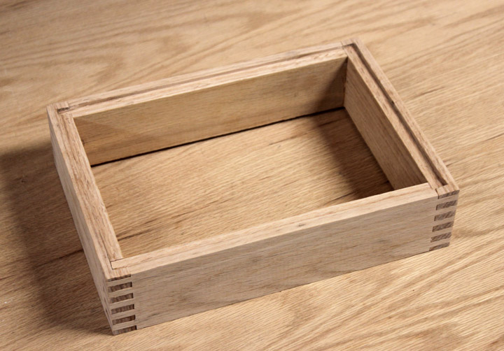
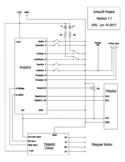
Next is to come up with a box to house everything and mount the front and rear panels, and here is another place where you can get creative. Sheet metal, plastic, laser cut plywood, whatever matches your skill set. I have even seen cake pans used to great effect for something this size. In my case, I wanted something a little more "woodworky" looking, so I cut a box using some 3/4 inch oak and made some box joints. On the top and bottom of the box I routed a rabbet and chiseled out the corners for the front and back panels to rest in. The outside dimensions of my box are 11.25 by 8.00 by 2.75 inches and were chosen to fit the panels, but in retrospect I could have made both the panels and the box a little larger, say 12x9x3. The rear panel, above right, was cut to fit and the holes drilled manually where needed. Two holes for grommets were provided, one for the power cord, the other for the stepper and limit switch wires to the lift. Because of the way that I plan to mount the box on my table I wanted the power and stepper wires to leave from the back panel, but you may need them to go through one of the walls depending on your mounting scheme. Other holes were drilled as needed to provide mounting for the Arduino, and some more nylon spacers were used to mount it. The box got a coat of some Danish Oil for a little protection. Later, I decided I didn't want the probe jack on either the front panel or the back of the box, so I mounted the jack on a plate that was placed on the side of the box over a hole to accommodate the jack. Depending on how you want to mount the box onto your table, you can place the jack accordingly. Fig. 19 Above shows the schematic for the project. The LEDs are powered by the 12v supply and need 20ma or so to work, so that means those resistors (R1 and R2 above) should be about 600 ohms or so. I chose to attach the current limiting resistors directly on the leads of the LEDs and cover them with shrinkwrap. Other than that, the rest of the point-to-point wiring is very straightforward. Normally, there would also be a pull-up resistor on each switch input to keep the input locked high until the switch is thrown, but the Arduino nicely provides that for us under software control, so that means that all switches will normally been seen by the software as HIGH, and will go LOW when the switch is thrown. The speed control is R3, the linear 10K potentiometer mentioned above. The probe box, its plug and jack, three wires, and two resistors are optional and can be added later at any time. Note: If you want to see the schematic close up or any of the images on this website in a larger format, you can. If you are using Firefox or Internet Explorer, right-click on the image and select "view image..." If you are using Chrome, right-click on it and "open image in new tab..."
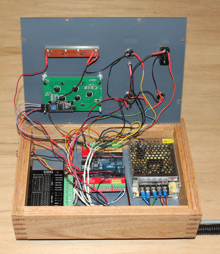
Fig 20 Above shows the wiring before (ahem) better cable management was employed. I used shrinkwrap on all soldered connections, and a length of loom for the wires to the router, but with the screw terminals it went pretty quickly. In order to verify the wiring to the switches, potentiometer, and probe, a simple diagnostic program called ButtonTest.ino is also provided in the download distribution that only requires the display and switches to be hooked up to the Uno. Pressing any button or switch, including the probe contact, limit switches, and speed setting is shown on the display, thus insuring that all is working as intended. If that program demonstrates the correct functionality, all that is left is to wire the stepper driver and motor connections, and you can compile and load the ArduLift program into the Uno from there. Directions for using the diagnostic program is provided in the download file. The TB6600 driver should be set to 8 microsteps, so its switches should be set to SW1 off, SW2 on, SW3 off. Also, the current should be set to 2.0 amps, so SW4 on, SW5 off, SW6 off.
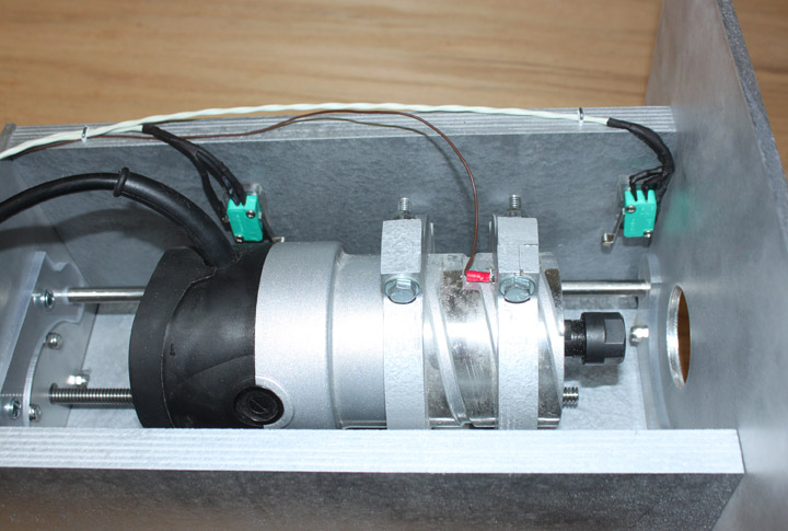
Fig. 21 The wires from the control box to the lift have the limit switches on one end, as well as the wire that goes to the router case (or a bit clip if there is no case continuity.) After knowing approximately where the limit switches were to be positioned, shown above, I made up a wiring harness out of some shielded twisted pair wire I had on hand. I chose to attach the current limiting resistors on the lugs of the switches, just like I did on the other switches and the LEDs. Using the screw terminal add-ons for the Uno, the only soldering needed is for these pieces, and each lead is covered with some shrink-wrap. The probe wire is attached by using a red spade connector on the end of the wire, and clamping it in place against the router body before tightening the router mount bolts. The other four wires are to the steppers and I used more of the shielded twisted pair wire for those. For the stepper I used (57BYGH213) the Red/Green was one coil pair, and the Yellow/Blue was another.
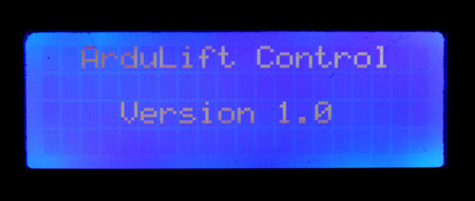
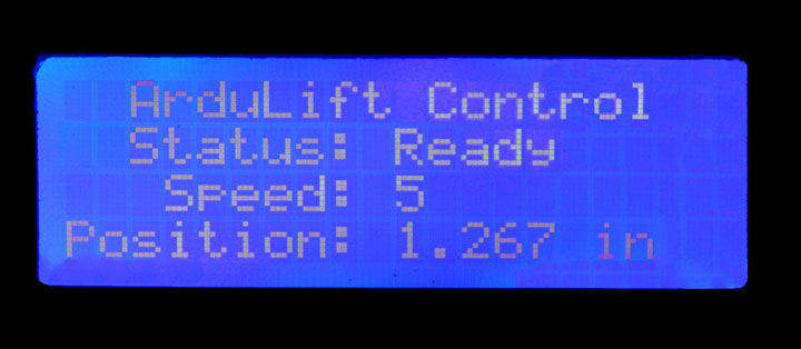
This project was written as an article and published by Digital Machinist magazine in the Summer 2018 and Winter 2018 issues, and the Arduino software is available for download at their website here. When you go that page, scroll down to the Summer 2018 issue, and click the link called "DM13.2 Liming" and the download should commence. Once the wiring is complete, you can power up the system while the Arduino is connected to a PC via a USB cable. At the time of writing, the ArduLift software was tested with version 1.8.2 of the Arduino IDE, but check the ReadMe.txt file in the software distribution for any notice of later versions of the ArduLift software or IDE compatibility. More information about how to install the IDE and getting it to load the blink program into your Uno is available on the Arduino website, and there are also many videos available with more instructions. The ArduLift software uses a library for the display that comes with the IDE, so no other software is needed. Once the blink program is working, compile and load ArduLift.ino into the Uno. Once that is done without error, the only other troubleshooting you may need to do is to verify the wiring against the schematic. The threads per inch for the threaded rod I used is 12 tpi, and this is reflected in the ArduLift.h file. If you use a different tpi, you can change the LiftThreadsPerInch variable to your new value in the file before compiling. That is about all you would need to change in the software. When the ArduLift software begins, you should see the splash screen on the display for a few seconds, showing the version number as in Figure 22. Next you should see the operating screen, shown above on the right. This screen displays the status, speed setting, and current position (which by default is set to 0.0 when power is applied) of the router bit in either inches or millimeters, determined by the UNITS switch position. By pressing the UP and DOWN buttons, you can move the router carriage up and down until the limit of travel is reached, as described before. When you first try the lift, if the router wants to go in the opposite direction from the UP and DOWN buttons, reverse the two pair of wires going to the motor to reverse the direction of travel. If the speed knob increases going the wrong way from turning the knob, simply reverse the wires going to the non-wiper leads of the potentiometer. The Uno has several limitations, but the relevant ones here are the number of I/O pins available, and the amount of RAM for use by the program. This design uses all of the available pins, and is close to using up all the RAM. The RAM issue is mitigated by making sure the majority of constants are placed in EPROM rather than RAM, and not incorporating any large memory allocation schemes or calling deep stack or recursive routines.
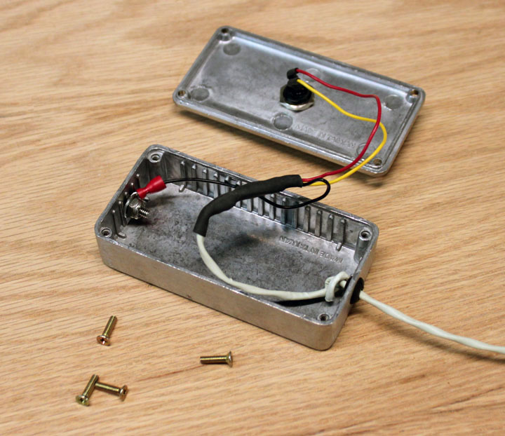
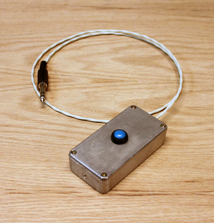
I have provided an auto-zero function, ala CNC machines, where you place a flat metal probe over the bit opening on the table and then press a button that causes the router bit to rise until an electrical contact is made between the bit and the metal probe. The bit then immediately stops and its position is set to zero. I describe this probe below. However, making one of these is completely optional. If you take a moment to recall how you set the height of your router, there are two main ways - one is where you simply eyeball the bit position, as in the case of setting the height of a round-over bit. You may want the bottom of the roundover curve to sit just a bit proud of the table surface, which will leave a slight ridge on the finished piece as a kind of witness mark such that a slight wipe of some sandpaper gets rid of it. Or, you may want it to sit perfectly even or perhaps a bit lower for a lot of other reasons. In any event, setting this height is largely a matter of getting a sight picture that you are familiar with. On the other hand, if you are using a milling type bit in the router and are cutting rabbets with it, the height represents the depth of the rabbet which often needs to be fairly precise for a good fit. In that case, a zeroing probe would be really useful if you don't already have a height gauge. In other words, whether or not you need a probe depends on how you use your router. For my part, I will make a probe and support its function in the code, but its implementation and use will be optional without software modification. The probe itself is very simple - the main challenge is to get the bit in the collar of the router electrically connected with it. Some routers have electrical continuity from the outside case of the router to the tip of the bit. In that case, all we have to do is connect the case of the router to the input. However, some routers are "double insulated" and/or use ceramic bearings, meaning there is no electrical continuity between its case and the bit. Test your router with a multimeter and see which is true for yours. If you have continuity, all you have to do is attach a wire to the case and you are done. If not, you will probably have to have an opening in the table top large enough to get a clip down onto the bit or its collar. This can be done with a mounting plate that has a replaceable insert. To make the probe, I used an old-school 1/4 inch stereo jack and plug, some 22 AWG three conductor wire, and a push-button (I had all these on hand,) and a small die cast aluminum project box (about $5 on Ebay), as shown above. The box can actually be of any material, as long as its bottom surface is flat, electrically conductive, and has one of the three wires connected to it. The other two wires go to the push-button. You could save yourself the cost of a plug and a jack by wiring the probe directly, but I wanted it out of the way when not in use. I wired mine with the box case wire going to the barrel, and the two switch wires going to the tip and ring of the plug. I mounted the jack on the side of the control box using a 1.5 x 1.5 inch plate of aluminum sheet metal that was screwed onto the wood, not shown above. Another option is to simply forego the jack and plug and wire the probe directly into the controller box. In that case, you would need to provide a hanger for the probe on your router table to make a place for it when not in use. The instructions for using the probe are simple: you lower the router until the bit is below the surface of the table, plug the probe into its jack, place the probe box flat on the table surface over the bit, making sure the table surface is clean, and press the button on the probe. This tells the Arduino to raise the bit until it senses another "switch" closure, which is the bit coming into contact with the box. The motion immediately stops, and the current location in the window is now set to zero. Unplug the probe and you are ready to rock. Again, keep it simple. Also, you can always check that the probe is working correctly by raising the bit above the surface of the table, and then lightly lay the probe box over the bit. An asterisk should appear in the right of the upper line of the display, indicating an electrical contact has been made between the probe and the bit.
Fig. 26 Above shows the completed lift, ready to drop into the table along with its probe. The table will provide two switched outlets, one for the router and one for the controller. The controller box will be hinged on the side of the table. I am really looking forward to using this thing as a matter of routine! Comments may be directed to gary at liming daught org. Thanks for viewing this build log! |
||||||||||||||||||||||||||||||||||||||||||
 --------