

Fuel System
Received the basic fuel kit (tanks, rubber hose) for the wings. Not real enthused about the rubber hose and garden hose style clamps with it, and I am wondering if I should use aluminum tubing. Also, I am wondering if I should buy, build or ignore the extended fuel tanks. Having the option to use them is nice, only penalty is cost and the weight of the tanks and unusable gas. $1000 seems like a lot, though. Need to do some asking around.
May 25, 2001
I did find out something out about how scratch builders make their tanks, and I decided to have my aux tanks made. That experience is here. I have heard good things about Swagelok fittings from other builders, so I will probably use those at least inside the wings where they will closed up.
I am worried about the way the wing skin just lays over the filer neck- any gap (and there is sure to be some, the way skin comes down over the neck) allows spilled gas to run into the wing section, so it must be sealed. I asked the flying list members if they experience gas coming out of the vented fuel caps, and they said yes. I will ask the list how they've sealed their tank necks.
June 11, 2001
Last week on the Zenith list, Bill Morelli put up an idea to seal the filler necks - talk about timely. His site is here. Mine turned out like the ones below before trimming. I used .025 3003 aluminum - it is soft and is used elsewhere for fairing material.. The hole in the oak board is 2 3/8" with a 1/4" quarter round routed edge and the hole in the fairing piece was a tad less than 2 1/8". I cut the holes slowly in the aluminum with a fly cutter in a drill press at low speed, and even then sacrificed a few pieces in order to get the hang of it. It's not quite like drilling aluminum foil, but close. Then they are carefully centered on the board and holes are drilled in the corners and brads used to nail down the pieces while hammering.
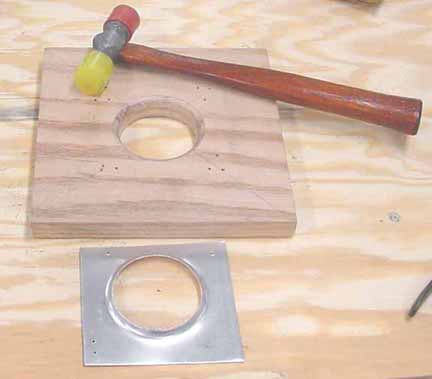
From here, I needed to determine the outside edge. At that moment, I finished the cold one I was drinking, and noticed the diameter of the glass was just about right, so I put it over the filler neck, and was just the right outside diameter I was looking for. Sometimes you get lucky! I put the glass over the flanges and ran a sharpie marker around it, and then cut and filed:
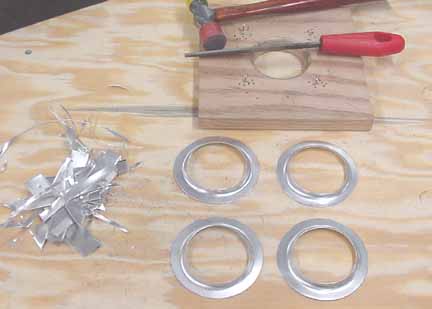
Four filler neck fairings! If you make these, do not press one all the way down on a filler neck to test for fit - I did, and ended up having to destroy one in order to get it off! You can set one on top of the neck to see how it will go, but wait until you're ready to seal it before pressing it all the way down. Mounting them to the tank will be done with some fuel resistant gasket sealer. All four of them weigh half an ounce. This was one evening - call it 3 hours. Thanks for the great idea, Bill!
June 15, 2001
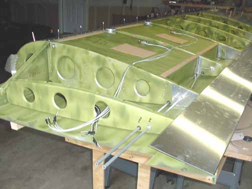
Here are the fuel tanks in my workshop: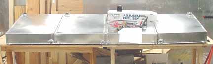
Next step is to install a VDO gauge sender in each of the tanks. The stuff on the tank is a Mitchell gauge hooked up to a power supply so I can check the travel of the sender float against that of the gauge. I think I will look at using a different gauge as I just don't like the way it reads.
The ZAC drawing says to locate the senders below the filler caps, 65 mm from the edge. It seems like this would make the readings bounce around more during turns than if they were located in the center. I will ask ZAC. About one hour fooling around with the gauges.
Each tank holds 14.5 gallons, or 58 gallons total - about 348 pounds of fuel.
June 30, 2001
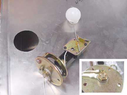
I installed all four of the tanks with the VDO fuel senders. I didn't trust myself with a power tool to cut the tank, so I just drilled a 1/2" hole and used the Jilson tool to nibble out up close to the circle line and filed the rest. The senders needed to have the tops cut off flush with the threads of the large center nut, as shown in the insert below. The wires were crimped and covered with heat shrink, and the nuts had blue Loctite in the threads. 9 hours.
October 24, 2001
Back in June I sent back the Mitchell Gauge and ordered an ISSPRO from Chief aircraft. Unfortunately, they were backordered until today. I am glad they came, though. I like the face because they give 250 degrees of swing on the needle, and since fuel management problems are common, giving the gauges as much visibility as possible is a good idea. For the same reason I am going with one gauge per tank, instead of switching them.
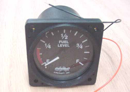
However, I hooked one up to one of the right wing tanks, and it read backwards - it read full when the sender was in the empty position, and vice versa. I removed the sender and reversed the float arm, and it was ok. The other tank read the correct way, as well as the other senders on the left wing. Just goes to show you that it pays to check on things as you go along. In the photo above, the orange and black wires are for the internal lighting, and will later be connected to the dimmer.
One other problem - they didn't read all the way empty when the tank was sitting normally, and pegged a bit past the F mark when I held the tank upside down.. After playing with the sender arms and adding a 22 ohm resistor in series with the sender, they read right on E when the sender was at the bottom of the tank, and on F when at the top. As a bonus, the needle drops a bit past E (as in the above photo) when powered off, so I can tell if the gauges have power with or without gas in the tanks. I will put the resistor in line with the sender wire just before the gauge. With a combination of moving the float arm so that it tops out and/or bottoms out where you need it to, and adding a series resistor with the gauge, you can get the gauges to read E when empty, and F when full.
As a result of all this, I highly recommend you get at least one of the gauges you are going to use and hook them up and test each installed sender before putting the tanks in the wing.
Here, the aluminum leads from the tank are ready to hook up to the cabin plumbing.
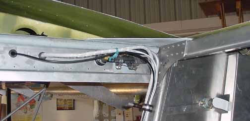
Above is how the fuel comes from the wing tanks down the cabin side - the aluminum leads from the tanks are fitted with a piece of hose and some brass right angle fittings that then fit onto 3/8 fuel lines that are bent to go down the side under the front seats to the fuel sumps. The black line is the video cable, and the white wire is a bundle for the lights and fuel senders. This area has a cover that goes over it.
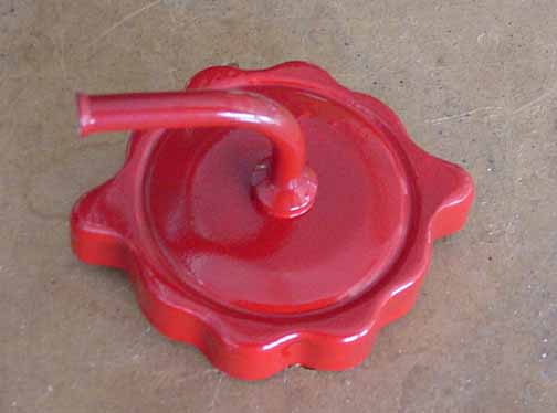
Above, I've taken a non-vented fuel cap from Wag Aero which fits the filler neck, and drilled a 1/4 inch hole in the center. I then took a 3 inch piece of tubing, flared one end, bent it 90 degrees, and inserted it into the hole. Frank Kerner made a collar to fit on his lathe for me, and it on the tube was silver soldered (brazed) onto the cap after making sure the vent tube was aligned into the wind. I then powder coated it red, and made three more. This type of vented cap should provide some measure of positive tank pressure.
![]()
![]()
Images on this website are either Copyright Zenith Aircraft Company and used by permission or are copyright Gary Liming