

Fuselage - 10th Page
Something I had done earlier but didn't document was to fit the instrument cover over the firewall and instrument panel with the cabin frame in place. This requires cutting holes for the cabin frame to go through. I found it helpful to start with stiff cardboard to place the cabin frame holes, just cutting rough holes at first, then I clecoed the template onto the firewall, and then made a snug outline with tape. By the time I took this picture, some of the tape had fallen off, but you get the idea:
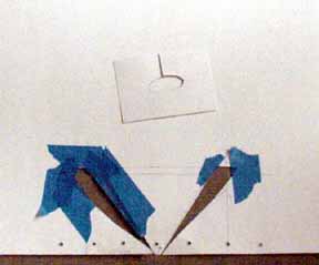
Then I cut the slots and clecoed the cover into place:
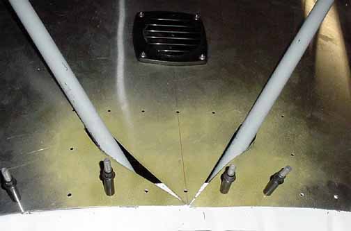
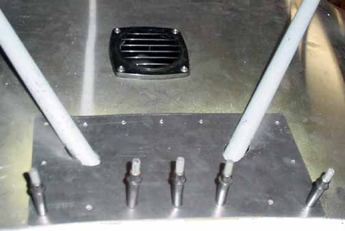
Here, I've also added a vent plate that I got from a boat store to provide a ventilation path for the avionics stack. Also, I've predrilled the holes for the top cover plate. The top cover plate is just a rectangle that covers the slits for the frame. I made a temple for the ovals the pipe makes when going through at an angle, as shown in the previous photo. This I used to make the holes, then I primed and put the top cover on:
You can't see them well in the photo, but there are slits from the cabin frame pipes straight back to the aft edge. All this get covered with some kind of non glare fabric, at least, that part that is inside the windshield. These pieces will be among the last pieces riveted since it makes getting behind the instrument panel very difficult afterwards.
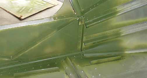
Another detail area - the cabin side is prepared for the kick panels. I've added some "L's" along the floor and a small one right under the end of the frame tube, which allows the kick panels to have something to attach to. This is optional, but does prevent the kick panels from moving when moving your feet around inside the cabin.
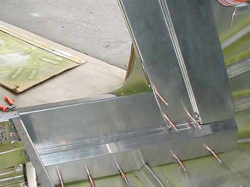
Here the kick panels are in place. Later, after the wires and tubing have been run behind there up to the instrument panel, the kick panels will be riveted in place and covered with cloth. The floor will also get a vinyl covering.
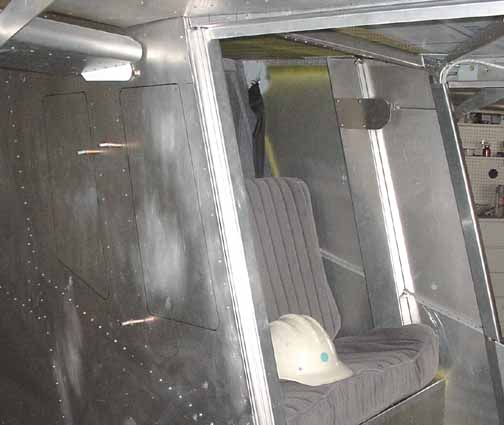
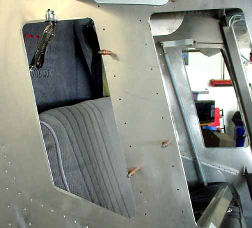
Above, the flaperon control rod covers are in place, waiting to be covered with fabric before riveting. I also added some Ben Haas style covers for the flaperon control horn - these serve to shield the control arm as well as provide a cover for the inspection hole I've cut into the vertical covers. Also, the windows are ready to cut out, as soon as I make up my mind what kind of shape I want them. I hit my head enough on the flap support struts that I've taken to wearing a hard hat while working around the wings.
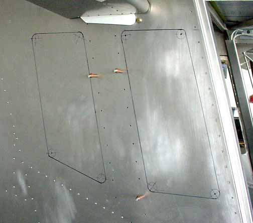
Here, one inch circles and their centers are marked and drilled. They will widened with a step drill.
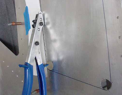
After the corner holes are drilled, the window is cut out using the Jilson tool. The good edge is protected by taping a strait piece of poster board along the cut line. The inside edges are then filed and deburred.
Next, the edges are beveled with a tool for that purpose (upper left of photo.) This will help the window edges to lay down on the plexiglass and form a better seal. Next, the plexiglass is mounted and riveted.
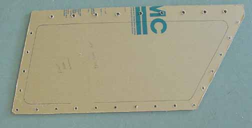
The plexiglass has been sized and drilled with a 3/32 hole, then removed and widened with a 3/16 hole, as per the directions. Do not go by the lines that come drawn on the plexiglass, but use measurements directly from the windows.
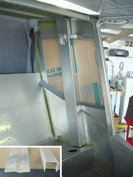
Here, I've made some trim pieces for the interior side of the plexiglass to rivet to. In the insert photo, there is a piece with an 1/8 inch joggle (made on my small 18 inch brake) that is used on the aft and top edges of the rear window. The bottom of the windows have sills, made by the U shaped channel on the right, 20 cm on a side. In the main photo, the sills have been covered with fabric. .016 panels covered in fabric will placed over the areas under the windows, along with some 3/4 inch sound deadening foam. Also, the flaperon control rod cover will be covered in fabric before riveting.
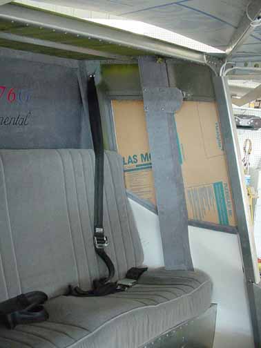
Above, the control rod covers have been covered in fabric, and templates for the bottom panels have been sized, waiting until I can get some .016 for covering. The areas above the windows will also be covered in fabric. The cushions are in place, and the seat belts have been installed. I will wait until the paint job to remove the paper covering on the plexiglass. You can see the Lexan sky shield in place. I plan on using bolts along the rear edge, making it easy to replace.
![]()
![]()
Images on this website are either Copyright Zenith Aircraft Company and used by permission or are copyright Gary Liming