

Instruments Page 4
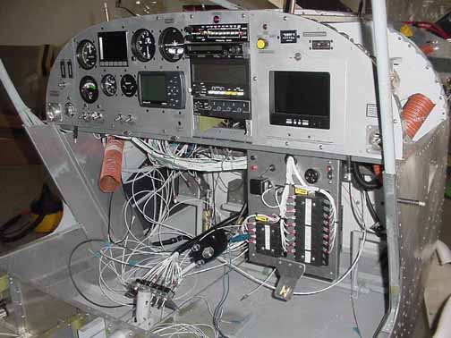
Here, the wiring is pretty far along. At this stage, most of the wires are run, and each component or subsystem is checked for proper operation. After the checkout, the wires will be bundled and placed into split looms. I use bread sack ties to keep bundles together temporarily and will replace them with cable ties.
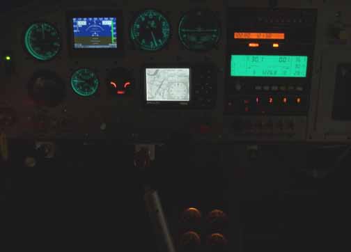
Here is what the panel looks like in the dark, although not a great picture. Having the three channel dimmer circuit really helps to make the incandescent, electrolumenescent, and Nulite AC rings all dim with the same knob at the same level of lighting. The only instrument above not lit is the LRI, so I may add a post light for it. The flaps and trim indicators are on the far left. Also, at the bottom of the photo is part of the fuel gauges, also dimmed to the same level. Not shown is the mag compass, which also has a light, but will be mounted on top of the panel cover and connected to the same dimmer circuit. Since the video cameras are of little use in the dark, I didn't include them. Can't wait for some night flying!
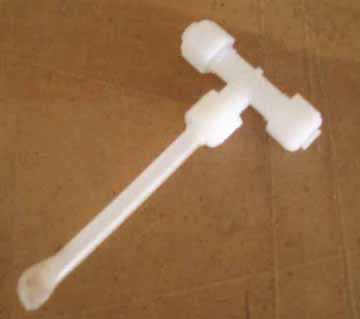
In hooking up the pitot/static system, I knew that I was going to have to have the altimeter and transponder encoder checked, so I added the above "T" to both lines, placed just under the instrument board where I can get to the long tube above. For both lines, this "T" serves as a sump in case any water tries to get in through the lines, protecting the instruments. I made the tube by putting the end of the nylon line in a heat gun, and then smashing the end with a pair of pliers. This forms an air tight seal, but provides an easy way for the calibrator to get at the lines to hook up his equipment (needed every 2 years) as well as providing an alternate static source by cutting off the tip in an emergency.
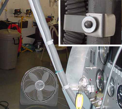
The pitot and LRI lines needs to find a way from the wing down to the panel. There just wasn't any room in the door column, so I encased them in some wire loom and made some brackets to hold them in place. The brackets are just some "L" of .025, and are riveted to a nylon "P" clamp around the loom. They will be riveted in place when the windshield is attached.
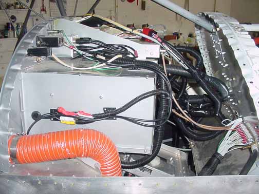
Above is a shot of the sleeved wiring, allowing enough slack to pull out the individual subpanels. Above is the pilot's side.
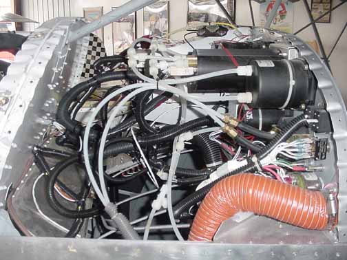
Same, only the copilot's side.
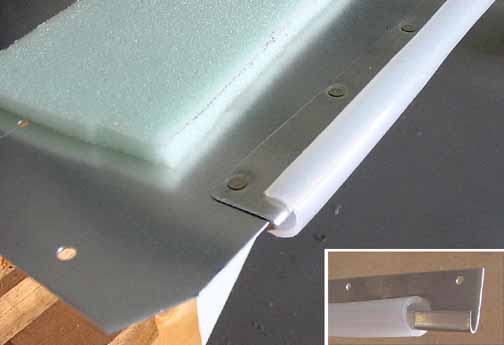
The instrument panel cover is just an edge of .025, so it would be like a knife in an accident. Also, there is very little support for this edge should someone decide to lean on it while entering/exiting the aircraft. The way I've chosen to provide a better edge is by taking a 1 1/8th inch strip of .025 6061 by 51 inches long (sorry about the SAE units) and bending it back along its length, making a 3/16 lip. I then cut a piece of 3/8 inch nylon hose and sliced it lengthwise, making sure the cut was kept centered down its length. This is shown in the insert of the picture above. I then flush riveted this strip along the edge of the panel cover (or glare shield.) I then cut a 2 3/4 inch strip of 1/4 inch upholstery foam 51 inches long, which I will wrap around the nose. The aluminum strip really reduces the cutting potential, and also provides a stiffener for the whole cover edge.
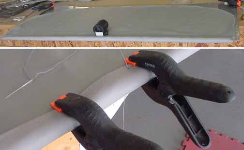
Above, I've cut a width of leather 51 inches long. The width is critical, since it determines the tightness of the fit around the foam. The width included about 10 mm that was wrapped back and glued along the length for a finished edge. I drilled small holes every 50mm around the panel edge for the stitching, as well as poked holes with an awl in the leather every 50mm as well. I then saddle stitched the leather using upholstery thread, as shown above. The finished edging is shown in the upper picture. An oversized piece of leather was also stitched into the seam. Later, it will trimmed around the windshield and glued onto the aluminum after its riveted in place. The compass is also mounted. I haven't mounted the GPS antenna yet because I want to see if the steel cabin frame will interfere with reception first, and find a good reception location.
![]()
![]()
Images on this website are either Copyright Zenith Aircraft Company and used by permission or are copyright Gary Liming