

Instruments Page 3
July, 2003
Just got back from Oshkosh, I am rethinking the panel (again!) The Dynon electronic AH is nice, but it is a pretty small screen, and although I really like the software in Control Vision's Anywhere Map, there isn't any good way to mount it into the panel. So, I am thinking about doing something else.
October, 2003
Well, I've found out that the combination moving map and EFIS display from Control Vision won't be ready for some time, so I am going to use the Dynon D10 and Garmin 196 for the map/nav device. I was going to use Control Vision's Anywhere software (which I really do like) with the iPaq, but I don't like the iPaq - I don't like the battery hassle, it doesn't mount well on the panel, and you need to be able to tilt it in sunlight.
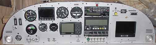
The panel will then look like this:
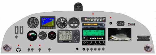
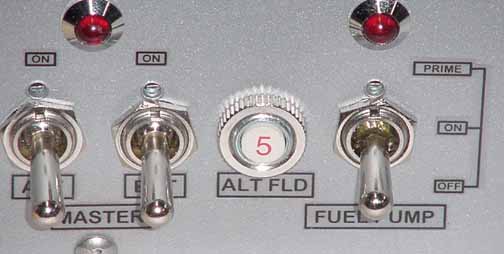
The red dots just represent LED indicators. The one above the ignition switch indicates the starter solenoid is engaged, and the one above the two toggle switches indicates the bat (master) switch is on, and the one above the next toggle indicates the boost pump is on. The one above intercom indicates low volts (usually an alternator failure - time to throw the ebus switch) and the one to the right over a knob indicates the wing cameras are on. The knob under it is the camera select knob. The knob under the transponder is the panel dimmer, and the one to the left of it is the cylinder select knob for the engine monitor. The 2 1/4 inch instrument left of the Garmin is the TruTrak autopilot. The map box shown is just a place holder for the map box monitor door. The knob above the door is the camera select switch, with a camera on LED above it. Also above it is the Hobbs meter and ELT panel.
This panel has lots of redundancy or failure tolerance. Airspeed, VSI, and altitude have both the Dynon readings and the "steam" instruments (although a common pitot is used for both airspeeds.) Navigation has the GPS, magnetic compass heading from the Dynon, and, of course, the whiskey compass. COM is a single unit, but I have a handheld in my flight bag.
Now that I've finally settled on a layout I think I can live with, its time to start making it. I've just about got the avionics stack done. It looks like:
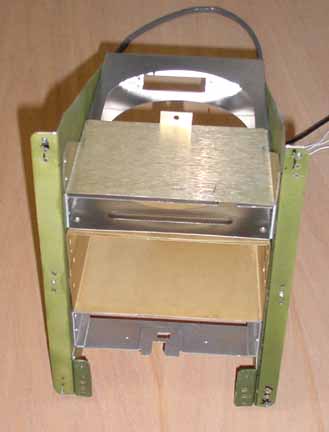
It was made from a couple of .025 pieces with a flange facing you. Onto this flange are installed some nutplates, as well as a couple of small "L's", also with nutplates, to provide an attach point for a switch panel that goes on the bottom. Then, one at a time, each component's cage with instrument in it was fitted, marked, and drilled. Then, the next component was added to make sure the faces all lined up depthwise. Doesn't look like much, but it was pretty time consuming.
I've decided to take a slightly different approach than originally planned. Instead of the small panels as above, I've decided to treat the entire instrument panel supplied by ZAC as a big mounting flange. This will enable me to make two separate panels, one on each side of the avionics stack, and allow me to screw them into place or remove them just as easily. I know that I like to try new gadgets, so being able to change out things seems pretty appealing. Riveting it all in doesn't.
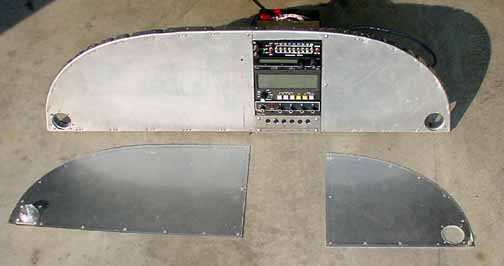
Here is what I mean. In the above picture, the avionics stack has been populated (except for the switches in the bottom switch plate) and nutplates have been installed around the perimeter of the original panel. Now I can cut out large holes in the panel flange, and be able to easily remove the things mounted on the two front panel pieces. I've also made "sockets" for the eyeball vents on each corner. One of them is mounted on the left front panel.
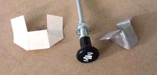
Although not strictly an instrument, the above does attach to the instrument panel. Rather than use any panel space for a control knob, which would have a cable that would make removing the panel difficult, I've decided to mount some of the control cables under the panel. Above is the paper template on the left, and a steel bracket made from that template on the right. The bracket will be drilled for the cable on the face, and drilled for riveting on the top, then powder coated and attached to the panel bottom tray. I will do this for the cabin heat, carb heat, and mixture controls.
Next, its time to make the mapbox. This will house not only sectional charts, but perhaps an mp3 player as well. Here is what I made:
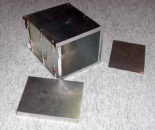
It is a basic box of 0.016 and 0.025 with flanges for mounting against the panel, and flanges to attach the back plate of the box, which is shown on the right. In the foreground is a shelf I will put in 2 inches down from the top to help organize things.
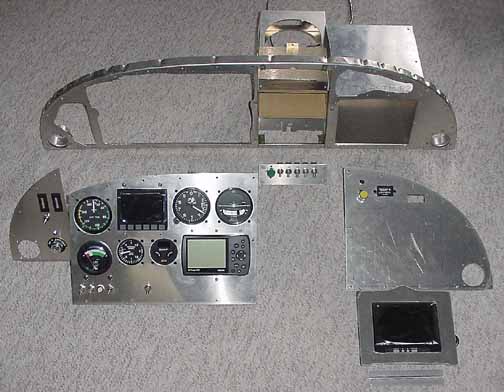
Ok, here it is finally coming together. On top, you can see the original panel from ZAC that has the avionics stack and map box riveted on. The rest of this panel has been cutout to allow all of the devices on the sub panels to be placed through. The larger front panels are nearly done with just about everything mounted, except the cutout for the map box door with the monitor built in. This door is shown in the lower right foreground. with its hinge. The air vents will be riveted in place after the subpanels have been painted.
The Dynon unit is mounting using their flush mount option so that the panel remains somewhat flat across its face. The Garmin 196 is mounted in a close fit hole matching the outline of the case, and then "knife edge" strips of 0.025 across the top and bottom of the case hold in it place by fitting in the grove formed where the two halves of the case come together.
The main reason for doing it this way is that each subpanel will be installed with enough wiring harness behind it to allow it to be removed and worked on in my lap in the airplane, or if need be, another subpanel with a different layout can be easily substituted. Another reason is the 0.025 panel supplied by ZAC was pretty thin once you cut all your mounting holes in it, so the 0.063 I used here supports the instruments much better.
A switch was needed to provide a place for the camera cables to attach, and select a camera and route the output to the monitor and the VCR jack. My simple one is:
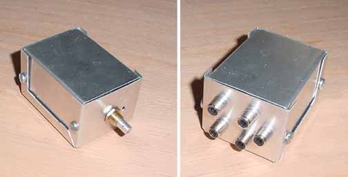
This is just a 3 position rotary switch in side a Radio Shack project box for shielding and it also provides a mount for the video jacks. There a are 3 camera inputs, and two outputs. This mounts directly on the subpanel.
I took all of the devices off of the panels, and prepped them for finishing. A friend, Ron Bessie, painted the individual subpanels for me, using a two part polyurethane auto paint, OMNI color #3261A with a clear coat over that, and then the panels were allowed to cure for several days. Then, they were ready to apply the labels. I used the freebie TurboCAD program (which I used to layout the panel and wiring diagrams) and made up my labels as a whole sheet. I took a tip from Sam Buchanan and drew boxes around each item which greatly helped in cutting them out and making them look good. I then used Avery #8665 label stock, which is a full sheet of clear adhesive labels. This is what the label sheet looked like:
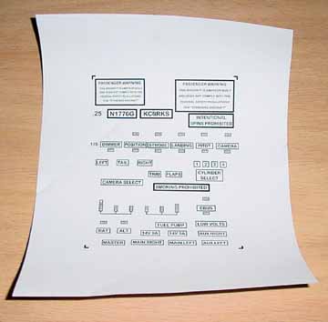
I printed the above on a laser printer, as I had been warned about not using an ink jet, as some of the ink from the ink jet may bleed into the top coat of clear finish that is applied over the labels. Then I cut a few labels with an Xacto knife and applied them on a test panel that was also painted. The only hard part is getting them on neat and straight. You may need several sheets of the labels printed up; I sure did.
I then sprayed different parts of the test panel with two different clear finishes, some "American Accents Clear Top Coat" matte finish, made by Rustoleum, and some Minwax Spray Polyurethane, satin finish. The Minwax layed on somewhat thicker, but was slightly yellow, so I opted for a couple coats of the Clear Top Coat. You must make sure the underlying coats have completely cured before spraying this stuff on.
Here is a close up of how the labels look doing this way..
Here the panel is just about ready to put in the plane. The monitor (map box) door is on with a Camloc thumbwing latch, and all of the "steam" instrument plumbing is done, much of the wiring back there is done, along with all of the wiring on the hinged fuse panel (not shown - see Electrical page.) Several wiring harnesses are also done. Total weight of the above panel as shown, 17.5 lbs.
Each of the panels can be removed and placed on the seat in the plane to be worked on. Although this used several more feet of wire, I think I am going to love that feature.
About the only thing not on there and wired is the cylinder select switch, which has a bunch of delicate wires going into a delicate switch, so I am still trying to figure out how to route the wires and provide good strain relief - I think I need to see it in the plane first.
![]()
![]()
Images on this website are either Copyright Zenith Aircraft Company and used by permission or are copyright Gary Liming