

Engine Monitor
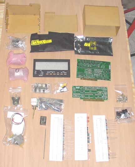
The components were very well packaged and well marked. The three white strips at the bottom are all the resistors, the small capacitors, and other components inserted into a sleeve, identifying each one! The plastic bag on the left is the optional fuel flow sender, and all the wrapped pieces above it are the engine transducers that come with the kit. On top are the case pieces, and the black plastic bags under them are the static sensitive IC's, and the display board, which is already completed using surface mount devices (SMD's) which are very tedious to mount without the proper tools. Of course, the green things are the double sided plated through and silkscreened PC boards, which appear to be of very good quality.
The first step is to put individual socket pins for each pin of all IC's. These pins come in a strip, and the manual says to cut them off to length and then insert them on the board. I tried that, but found it much easier to insert the strip into the board, and then cut off the extra length. After thoroughly checking each pin for straightness and good solder contact, the two boards looked like:
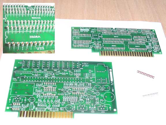
There are a couple of pin strips off to the right. You really need a head magnifier to mount these. Upper left is an insert showing a close up of the pins. This was tedious, but you learn what works for an efficient technique as you go. Although sockets are normally not used in avionics, the manual said these would provide very good contact, and greatly reduce the chance of any problem arising from static electricity damage during assembly. They are gold plated inside, but unless the IC pins are also gold plated, (they are not) that really won't help that much. Took 1 1/2 hours to degrease the PC boards, insert and solder the pins.
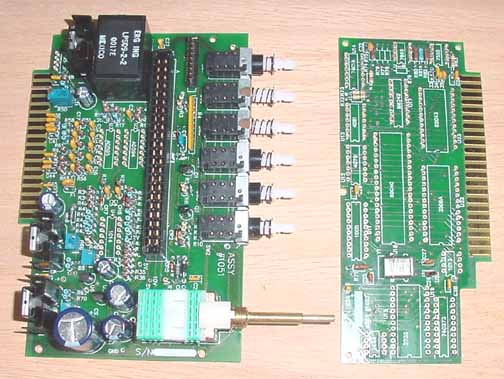
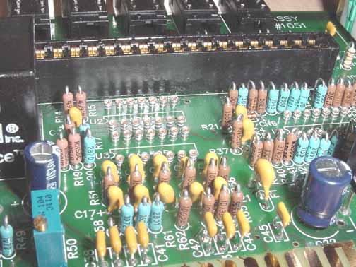
Above are the two boards fully populated and cleaned, but without the IC's inserted in the sockets yet. Below is a close up of the main board showing the precision resistors mounted upright.
The boards were thoroughly cleaned of flux with lacquer thinner, and carefully inspected once more. 9 hours more. Next, we test some voltages and insert the IC's. After the voltages are tested (they were right on the money), the ICs were inserted following anti-static measures which includes working on a grounded piece of aluminum foil, since many of the IC's are CMOS. The various layers of the faceplate were placed in the faceplate mount, including some very unusual zebra foam connectors that connect the faceplate to the display board.
Then, the boards were placed in the anodized housing and screwed in place, like below:
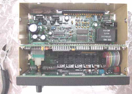
Finally, power was applied to the box, and the display lit up:
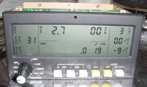
All the above values are normal with nothing hooked up yet, except the "gal", "Oil PSI", and AMP values were flashing, indicating alarm values, and this photo happened to catch them flashed off. Hooray! 3 hours of assembly to this point. Next step is to put it in the freezer for a bit, and then put it in a hot box for a while, and then calibrate it.
To return to the instrument page, click here.
![]()
![]()
Images on this website are either Copyright Zenith Aircraft Company and used by permission or are copyright Gary Liming