

Instruments
I am not sure what buying non-TSO'd instruments might mean in the long run. Also, after looking at a whole bunch of separate meters for engine conditions like rpm, oil temp & pressure, CHT and EGT, etc. the Engine Information System (EIS) which includes all sensors for $595 (for the O-360) looks pretty good - it shows RPM, dual EGT and dual CHT, hour meter, flight timer, voltmeter and outside air temp and oil pressure. This looks pretty good, but is all shown on a LCD display, and I have heard negative opinions about LCDs, like the sun can wash them out on certain angles, and polarized sunglasses making them hard to read. Still investigating.
March 12, 2001
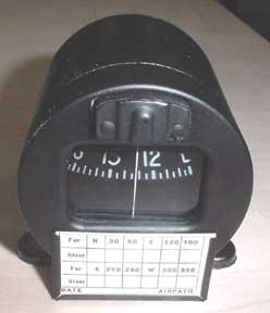
Bought my first instrument! At Central Air Parts (a local aircraft salvage yard NE of St. Louis) I found a 1997 Airpath traditional TSO'd compass, right out of a Cessna. I got it for $50, and I think it will go well in the plane. I found out that Airpath is right here in St. Louis. I've decided I want the compass mounted on the dash, and although I could have adapted a mounting for the one above, I decided on a different housing for it. I called Airpath, and they said "just come right over!" I did, and I met the owner who was a heck of a nice guy - his grandfather started the business back in the 30's. He showed me a bit of the assembly floor, and I saw many compasses being baked to a couple hundred degrees, cooled, and then frozen to 80F below zero! This was all part of their MIL SPEC QA procedures..
Also, he showed me a Rotorway helicopter kit he was building, which was fascinating, and he really understood the home builder. Anyway, he gave me a new dash mounted housing with correction card:
March 29, 2001
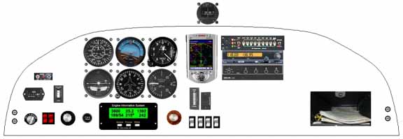
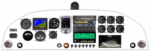
There is a great new tool on the web for doing panel layout. With it, I was able to do this preliminary design with the instruments I currently have in mind:
They didn't have the RST565 audio panel or the 801 panel layout when I got there, so I sent them a picture of them, and it was there in 10 minutes! Great effort and nice guys - Bill VonDane, Mike Nells, and Jared Boone.
On the panel, I have the compass mounted on top away from magnetic fields as much as possible. From left to right, pilot headphone jacks, starter switch, above a Hobbs meter and the ACK ELT switch, a battery monitor LED, below the Cessna style split rocker switch, throttle, carb heat, EIS, mixture, above the basic "six pack", a handheld moving map GPS display, below the mixture knob, trim leds and rocker switch and the light/pump switches. Above, the RST565, ICOM A200, transponder, and the funny looking thing on the right is a map box, and co-pilot headphone jacks. I still need to add the required passenger warning placard.
April 19, 2001
I have begun to reconsider the layout to accommodate flying from either side. It now looks like:
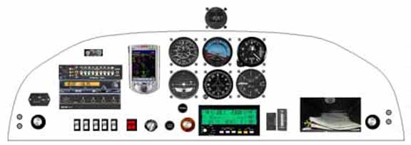
The changes are having dual throttles on either side, putting the six pack in the center, and a Rocky Mountain engine monitor instead of the EIS. The radios are now harder for the co-pilot to reach, but all the crucial instruments for takeoff and landings are accessible by both. Still considering this.
May 27, 2001
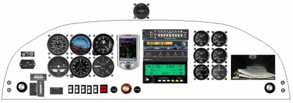
Nope, I don't like the way it scans - back to a more traditional layout, including 4 fuel tank gauges and a voltmeter, and ammeter.
July 2, 2001
I have settled on the Rocky Mountain Instruments micro-monitor, the green screen shown above. There were two main reasons I've chosen it - it replaces a host of engine instruments - tach, fuel flow, EGT, CHT, oil temp and pressure, OAT, flight timer, and volts. Another reason is the company has a policy of not starting the warranty clock until first flight of the aircraft! They certainly do understand the homebuilder. Also, and maybe even the main reason, is that the monitor watches all that data, and sets an alarm on them when they exceed a specific threshold. I think an embedded microcomputer will do a much better job of continually watching those instruments than I will, and it frees up my eyes for the sky. You can save $300 by building the kit, which doesn't seem very difficult - the manuals are on-line. The fuel flow is an option because the fuel flow sensor is expensive (about $100) but given one of the major causes of GA incidents is fuel management, I will gladly accept the help. For that kit experience, click here.
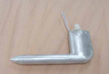
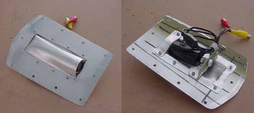
While Dave Zilz was at a local salvage yard he picked up two heated pitot tubes for us . Here's mine:

It is going to take some work, and I will need to change the angle of the mounting flange, but it still beats new pricing.
A little cleaning and brushing, and its ready for the mount and priming. You must make absolutely sure that the opening and the small hole on the bottom (provided for water that enters the tube to escape) are clear without changing their shape. Then, make a few parts:
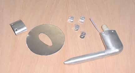
Then, prime and assemble:
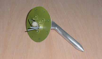
Voila! One heated pitot, ready to mount in the left wing. I got into making the round mount plates, so I made 4 for the fuel sender covers, and 2 for the camera mount, one for the camera, and one to cover it when not in use. I made these just right diameter to allow riveting over a 3 1/8" hole - the same size hole cut by the instrument panel hole cutter.
Here is the camera fixture:
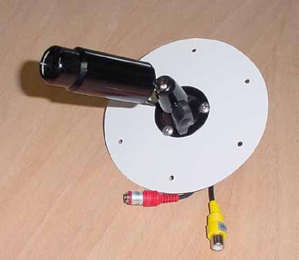
Since my color scheme uses white on most of the wings, I painted the mounting plate white, and primed the other side. I need to change the red connector to match the Molex connector I am using (they provide a positive locking) for the +14v power. Weight of the camera unit as pictured above with the power plug added is 5.0 oz. The camera itself is about the size of a roll of dimes and allows a full 360 degree swing around the plate. I plan to make a wing mount on the tip of the right wing, and mid-left wing. (See 2nd and 3rd wings page) A jack will be provided in the sill of the door for either mount, along with an audio jack from the intercom to provide a complete recording of the flight.
Above is another camera in a fixture I made for the tail - should be some spectacular shots of takeoff, as well as another way to "check your six." There will be a selector knob on the panel to determine which camera to view and route to a video recorder. (The above fixture and picture were done spring of 2003.)
November 5, 2001
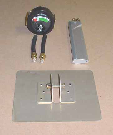
I have decided to include an LRI lift reserve indicator. It looks like an especially useful instrument for STOL aircraft. It is very easy to install, it comes with the items in the photo, except for 40 feet of polyflow 1/4 inch tubing (same stuff ZAC sends with the pitot) and the documentation. The two black hoses adapt the ports on the meter to the tubing. The unit is calibrated by adjusting the angle of the probe to the wing once the aircraft is flying. Wings page 4 shows installation of the probe in the right wing.
January 10, 2002
Yet another iteration of panel design incorporating the LRI and the Dynon EFIS D-10:
Also add some vents and decided to go with good ole toggle switches. With a magnetic compass, heading on the EIFS, and a GPS, do you really need a DG? Also without a vacuum driven artificial horizon, I won't need a vacuum pump and suction gauge. This does make the flight instruments more dependant on the electrical system, but with the essential bus design and annual battery maintenance, there should be enough juice on board to out fly the fuel supply even if the alternator goes out.
I am considering putting the pilot's headphone jacks down just behind the right seat, and the co-pilot's jacks down and just behind the pilot's seat. Easy to get to and the wires stay out of the way. Will wait until the seating is done to decide.
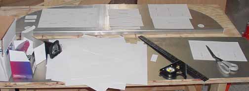
Another good thing to do is take a CAD program (like the freebie TurboCAD) and make paper templates for everything, and lay them out on the panel. Much better for figuring how how they play together, how much room is really needed, etc.
![]()
![]()
Images on this website are either Copyright Zenith Aircraft Company and used by permission or are copyright Gary Liming