

Wheels
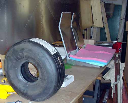
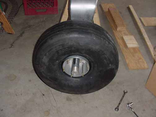
Picked up the landing gear kit and the engine mount at ZAC today. I've seen the tires before on on the demo plane, but they are BIG - 11 lbs a piece, and that's without the rim and inner tube. Also, the aluminum landing gear spring is HEAVY - 48 lbs alone. Can't wait for the bird to sit up on her own feet.
Also in the above picture on the right are the two seats, waiting to go to an upholsterer. The foam is some special (and a bit pricey) foam in three densities - the green layer is heavy density, the blue is medium, and the pink is light density. It's thermal sensitive and is called Confor foam. I saw the stuff at Sun N Fun, and it was very comfortable. From Wicks. The back will just have regular foam with some lower back support added..
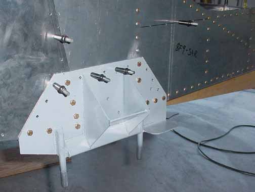
Above, the main gear support is 4130 steel and is primed and drilled into place and bolted. The holes into structural members get bolts, and holes into skin are riveted. The manual says all drilling is done from the inside of the fuse, and you need to do this to make sure the bolts come through on the center of the longerons, but I found it easier to drill through the longeron and get the hole in the support started at the right spot, and then remove the support and finish drilling it on the bench. Another tip - make sure someone looks from the bottom before you drill to see if the sides of the cabin are pulled together enough to match the bottom skin width. Using a ratcheting strap around the sides of the cabin at this point will help.
A word about drilling the 4130 - it is not at all like drilling aluminum, it is very hard stuff. Use high quality cobalt steel drills, and apply some oil to the hole while drilling. They make a cutting oil for this purpose, but I just used 3 in1 oil, or you could use motor oil - you just need something to carry away the heat. If it starts to smoke, you need more oil. The air drill did not have enough torque to drill this stuff. When drilling, it is important to get a feel for the pressure and speed needed on the drill. Too much pressure, and too much heat is generated and too much torque is required - too little, and the shavings won't come out. It is important to use a variable speed drill. Too fast, and the shavings come out in chips, not a nice continual spiral. Way too fast, and drill won't bite into the steel, it will just overheat and ruin the bit. Too slow, and the bit will bite into the steel too much.
Another word about this step - if you look forward to the section on mounting the wings (finish3of3-attach-wings.pdf - section 3 of the finish manual), there are instructions to drill two 5/16 holes in the gear supports where the struts go - if you wait to do that after the landing gear are on, you will have to remove the landing gear (again!) in order to do this. If you do it now, you will save yourself the tedious work of removing the landing gear while on the finished plane.
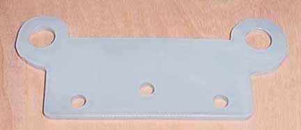
Above, I've made a tow bracket like I saw on the demo plane out of 1/8 inch 4130. There are many ways to solve this problem - some attach to the sides of the axle bolt, etc., but this one fits a Piper PA-28 type tow bar, which is just a handle with two bent 3/8 steel dowels or prongs that go into the larger two holes above. The two top holes are 1/2 inch in diameter that are 4 inches apart. The bottom holes match the holes you've drilled into the strut and fork. It added 3.1 oz of weight. I will either pick up a tow bar from salvage or make one that is light enough to carry in the plane. I cut it out using a metal cutting wheel in a circular saw, and shaped the edges with a grinder and file.
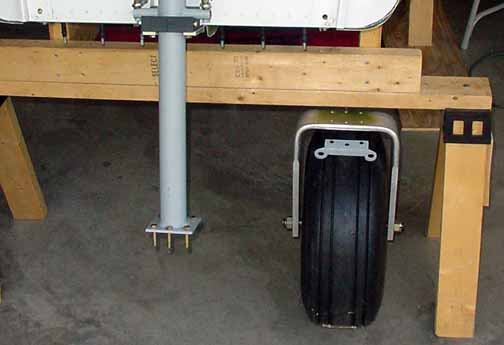
Above, the nose gear completed and waiting to be bolted. As you can see, the fuselage will need to be lifted a bit off the cradle before the nose fork can be attached, so I will wait until the main gear are on. The bolts are hanging down from the strut and will go into the fork, and then through the tow plate, which is just resting on the tire.
Getting the inner tube into the tire and centered so that the air nozzle of the inner tube is at the right spot was a bit difficult, but otherwise the Matco wheel was put in place very easily. Make sure you pay attention to how the wheel is put together when you take it apart. As per the recommendations of the manual, I made a center spacer for the axle out of the same 3/4 inch 4130 tubing that I used for the FHNSF. Also, I picked up a flyer from ZAC for the 8.00 x 6 Condor tires, which stated that the tires should be inflated to 35 lbs of pressure.
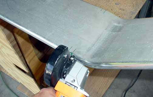
Above, I am cutting the notches for the bolts of the main gear support. These are just deep enough to fit, so you have to sneak up on it. Ideally, these would be milled out, but the angle grinder does a good job of cutting these out, just take your time and leave a bit to file it smooth.
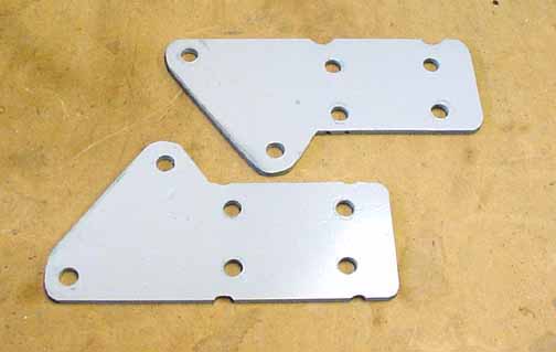
I was a bit concerned about how much of the main gear is cut away where the JD Murphy wheels are attached. These wheels have dual brake calipers, so they fit around the gear legs in a fairly small area. They have never experienced a problem in this area, so it can't be a deficiency, but it is my understanding that ZAC no longer uses these wheels or this attachment design, so you probably won't have to worry about it. I talked to Robbie Grove of Grove Aircraft, who designs this kind of spring gear for his customers, and I decided to add a steel reinforcement plate on each leg to make the joint stronger. It is 1/8 inch 4130 steel and both of them with the two attachment bolts add 17.3 oz. of weight. Maybe I'm just being paranoid about it, but this gives me a little peace of mind about it..
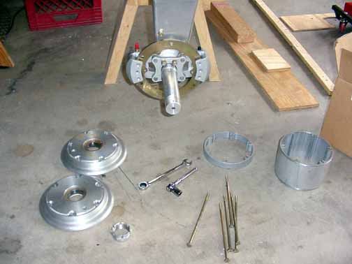
There is very little in the current manual about putting the wheels on, so I took these pictures. After the holes have been drilled in the leg according to the drawing, the bolts are inserted and the axle flange is placed onto the bolts, and then the brake disc and shoes are fitted onto the axle. Then the bolts holding the axle to the leg may be tightened as shown above.
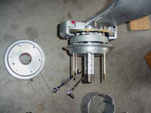
The next pieces are the long bolts that go through the disc. Onto these is the spacer ring that rides between the inside wheel hub and the disc. Then, the inside wheel hub goes onto the bolts as shown above.
Next comes the tire. First you need to take care to get the inner tube to rest inside the tire with the air valve centered inside the wheel. Then, I found it helpful to put a little air in the tube, just enough to push out the wrinkles of the tube, but not enough to change the dimensions of the tire. Then, I worked the air valve through the hole in the wheel middle, and put the extension valve on. Then I placed the tire and wheel middle onto the axle and long bolts as shown above. Finally, I put the outer wheel hub on, and screwed on the nut and inserted the cotter pin.
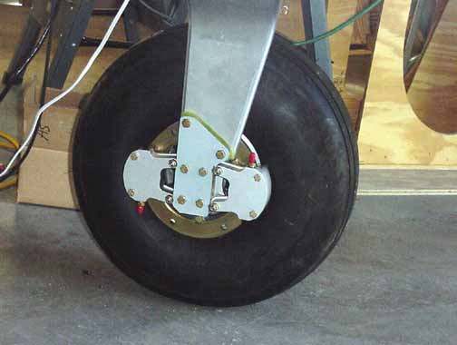
Here is the back side of the mounted wheel, showing the steel reinforcement plate in place.
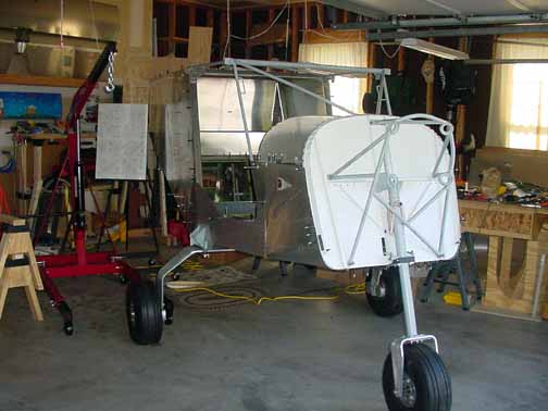
And here she is, standing up on her own three feet! There is not enough weight up front yet to balance, so she still needs the aft support, but this is an important milestone for me. No sooner than I got the wheels on, did the plane try to roll around the shop. I made some cheap chocks for it, shown here.

Here, I have run tubing from the brake master cylinders to the wheels. I routed the line inside the cabin as shown in the manual. On the wheels, you can route the brake line around the front of the calipers, or route it as shown above. This way seems to me to have less line exposed to possible weeds, etc. In the picture above, I am doing what is called "back bleeding" which is to force brake fluid (the red aviation kind, aka MIL-H-5606 hydraulic fluid) using a new, cheap oil can to pump the fluid all the way from the calipers up into the reservoir of the master cylinder. This way, no air bubbles are introduced. When full, of course, the oil can hose is replaced by the bleed screw and tightened. Also, I've safety wired the bolts on the calipers.
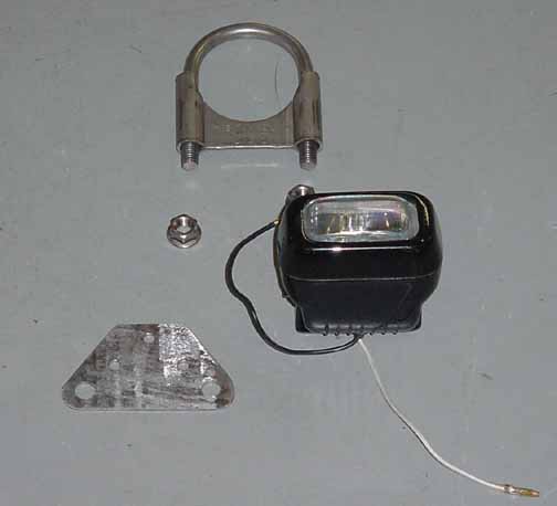
Above is my idea of a landing light - the light unit is a halogen fixture, and the U bolt and bracket is from McMaster Carr and is stainless steel, and fits the nose wheel strut perfectly - a 2 inch ID fit. The other piece is machined by me and both it and the U bolt will be powder coated, and the light attached with AN hardware.
![]()
![]()
Images on this website are either Copyright Zenith Aircraft Company and used by permission or are copyright Gary Liming