| Welcome to...
|
|||
| Home |
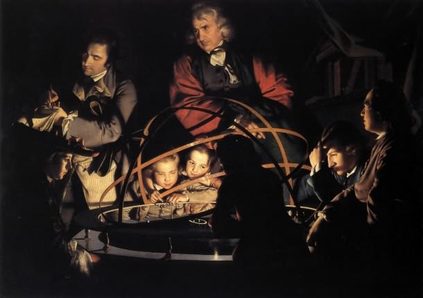
Fig. 1 This website is a log of my building experience making an orrery. An orrery is a mechanical model of how a selected group of astronomical bodies move and from which their movement across the sky may be explained. The first ones were ancient - the Roman writer Cicero, writing about the first century B.C., described one created by a Greek philosopher named Posidonius. One of the earliest ones built in more modern times was by George Graham and Thomas Tompion, who in 1704 commissioned one to be made in a London shop by a John Rowley. Soon Rowley received another commission for one from an Irish nobleman, one Charles Boyle, 4th Earl of Orrery and this one was so well received that the device became commonly known as an orrery. Figure 1* is a painting is by my favorite 18th century artist, Joseph Wright of Derby. Its full title is "A Philosopher giving a Lecture on the Orrery in which a lamp is put in place of the Sun" ca. 1766, and shows a scientist (the one in the red robe - they were called natural philosophers back then, not scientists) giving a talk on the motion of the planets. This device is a large example and shows how sunlight falls on various planets at different times. Although this looks quite wonderful, my goal will be to make a more modest example.
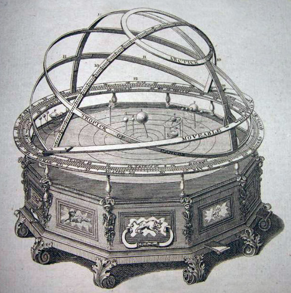
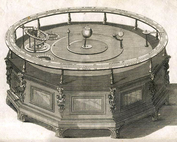
Figure 2* is an image of the one made by John Rowley that looks just about like the one in Wright's painting, and is more like what I had in mind, except on a smaller scale. You can see the hand crank on the left, and some sliding "tabs" on the right, of unknown purpose. Each panel of the twelve sided cabinet has signs of the zodiac on them, a nice touch. Ancanthus leaf legs and support figurines on each corner really puts this style over the top. Jupiter and Saturn show their known moons, albeit fixed in place. The earth appears to change its rotation, demonstrating the seasons. Bands showing the equator, tropic of Cancer, a movable horizon, and the arctic circle are very interesting, but I don't know if I'll include them. Figure 3 is an image of another early one made by James Ferguson, although less complicated by only showing Mercury, Venus, Earth and its moon. Clayton Boyer, renowned for his wonderful wooden sculptures and clocks, has designed a Copernican orrery on a desktop scale. A Copernican orrery is one like the above that is heliocentric, and demonstrates the motion of the six planets that were known to Copernicus - Mercury, Venus, Earth, Mars, Jupiter, and Saturn. Clayton sells the plans for his creations, and his design was very close to what I was looking for, so I ordered it. A photo of a completed orrery of Clayton's design is shown here. Another extensive builder of Clayton's designs, one who has also used a CNC machine to cut the parts, is John Tribe. John also contributed the "open top" layout to Clayton's design.
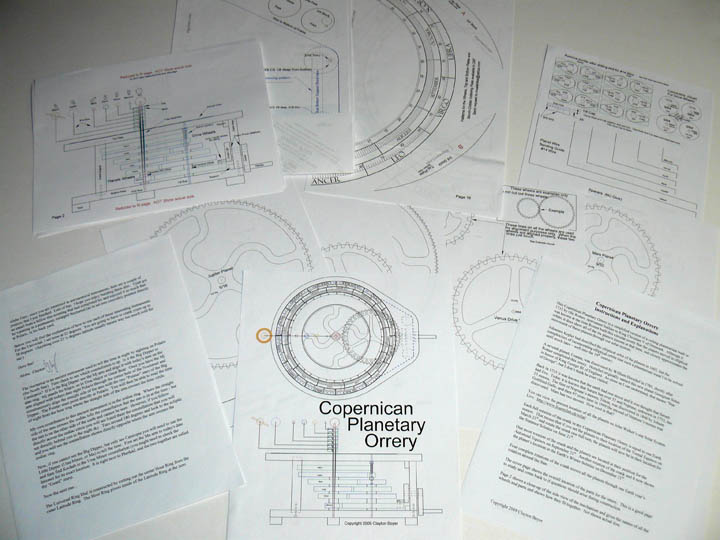
Fig. 4 The plans arrived promptly, and I spent some time with them. They consisted of a set of instructions and assembly advice, some drawings illustrating the overall fit and layout, and a set of part drawings at full scale. The parts need to be made to specific sizes so that they will all mesh for a smooth running machine. The directions call for you to glue the actual drawing for each part to the wood, and then cut them out using a scroll saw. Although many have done it this way, I would like to try using a CNC router machine. (More about that machine here.) Some of the parts are dimensionally larger than can fit on a single sheet of legal sized paper, so separate pages must be aligned and taped together. Clayton graciously agreed to provide drawings of those large parts in their electronic drawing format, a .DXF file. The next step is to convert the other parts to .dxf files as well. This was done by using a scanner and then playing with its settings to make sure the resulting images are the proper size. Next, I used Vectric's Aspire (This could be done in Vectric's VCarve Pro or Cut 2D just as well) to import each .jpg, create vectors from them, and load the remaining DXF files. Then I joined all the vectors for each part, got rid of any markings other than cut lines, and save each part as its own .DXF file. Then I can converted each one into toolpaths and a file the CNC machine understands, a G-code file.
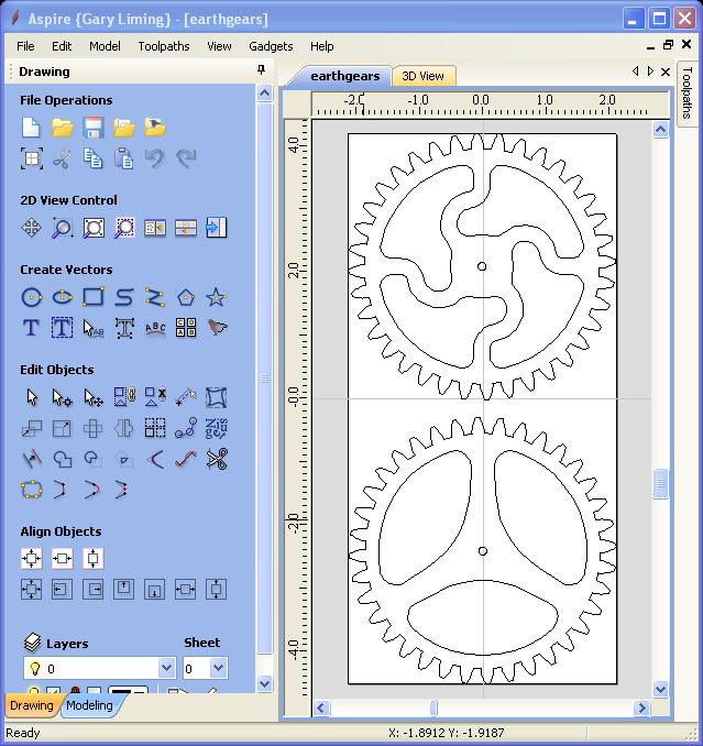
Fig. 5 Above is a screen shot of Aspire showing two gears, ones that represent the motion of Earth by the ratio of the number of gear teeth on the two gears. From here I generated toolpaths for the gears, combining parts and placing them on available pieces of material, including a small tab on the sides of each part to hold it in place while it is being cut. You don't want parts flying off while you are working! Above is a 6 minute movie I made of cutting some of the gears.
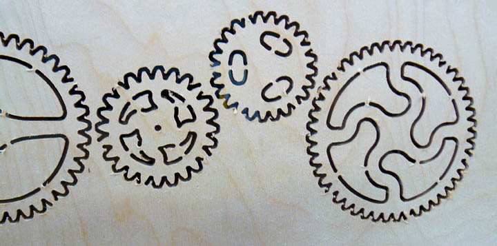
Fig. 6 Figure 6 shows what the gears look like on the bottom of the 1/2 inch Baltic birch plywood right after the router table is done with them. The holding tabs are visible, just waiting for a utility knife to cut them off, just like a modeler cuts the sprue off of plastic parts. A little sandpaper, and then they are ready to be fitted!
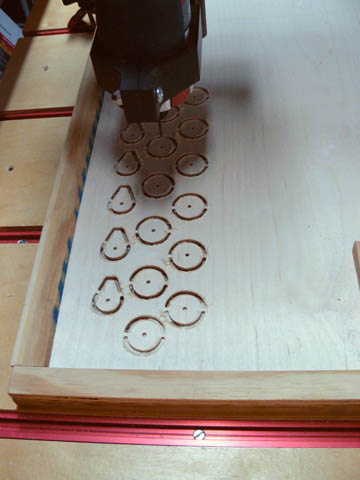
Fig. 7 Some of the smaller parts made from 1/8 inch Baltic birch plywood.
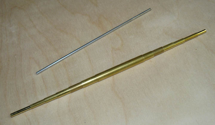
Fig. 8 The drive gears for each of the planets are turned in unison on a common arbor, the stainless steel rod shown at the top of Figure 8. Each of the planetary gears are turned on their own tube, with each one fitting inside the other, as shown by the telescoping brass tubes on the bottom. *Fig. 1, 2, and 3 are public domain images. All others are by the author. Vistor Map Comments may be addressed to gary at liming daught org. |