|
Page 3 |
|
| Home |
Fig. 17 Likewise, the top of the case is CNC'ed, trimmed, and routed.
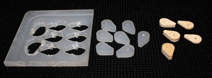
Fig. 18 At the top of each planetary tube is a hub connector into which the rod which supports each planet connects. The plans call for them to made from two pieces of plywood - an 1/8 inch and a 1/4 inch piece that is drilled out to accommodate the rod and then glued together. Those were shown in Fig. 7 and are above on the right after being drilled through. I found the result to be very fragile. I CNC'ed from a high density polyethylene sheet (aka, the corner of a kitchen cutting board I got at Walmart - it's a great material to use for some things and machines very nicely) and found that these work very well.
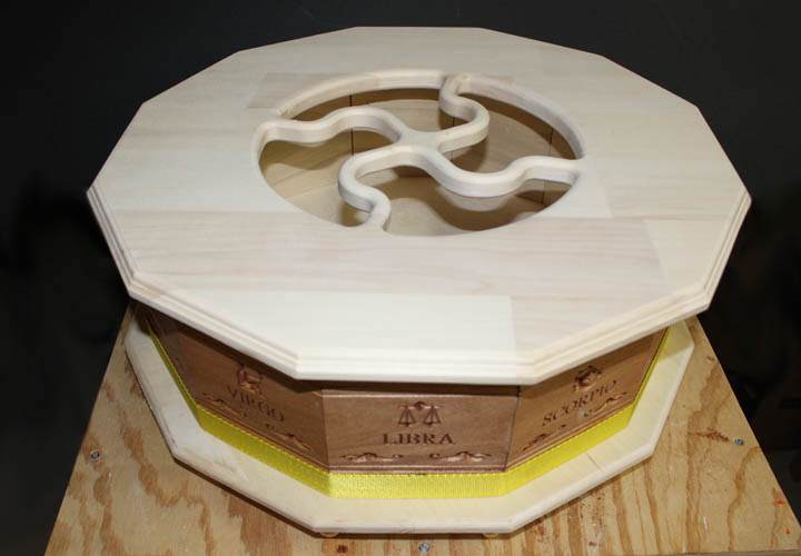
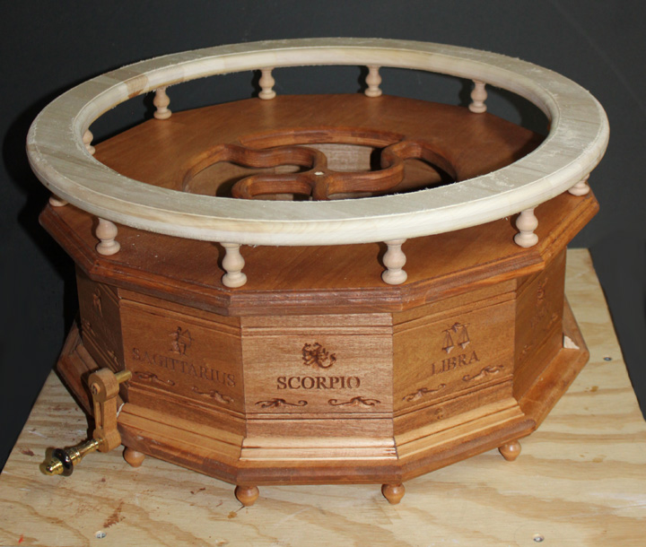
Fig. 19 Here, the lower case is about complete. The molding was a bit time consuming, but really addds to the look. Now, it just needs a rail like that shown in Figures 2 and 3, and the gears can be completed.
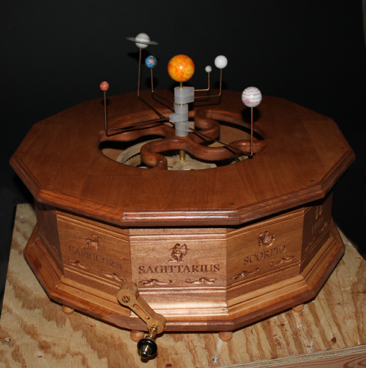
Fig. 20 Above shows the gears in place, the planets on their rods and plugged in, and the crank attached to test the motion. The crank uses two of the telescoping brass tubes left from the planetary axis, as well as a brass fan switch pull. Everything seems to fit well!
Fig. 21 Railing cut and fresh off the router, checking fit. Now it needs to be sanded and finish applied. Then onto final assembly! Above is a movie shoing the motion of the planets as demonstrated by this orrery. Thanks to Copernicus, Rowland, Holtz, and Boyer who made it possible.
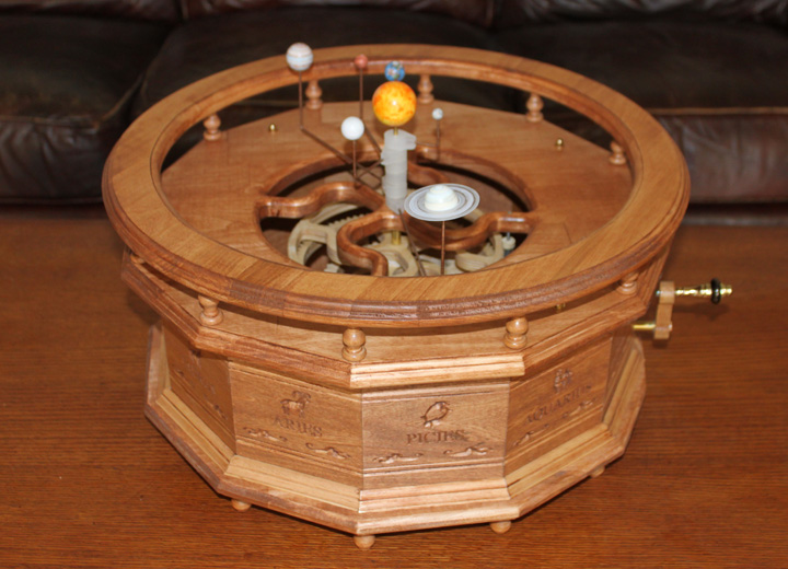
Fig. 22 The completed orrery. Thanks for visiting this website. |