

Engine
January 12, 2002
For the firewall, some stainless steel grommet shields are needed to pass wiring and tubing that won't let flames get through. Tony Bingelis shows a way to make some on page 54 of "Tony Bingelis on Engines" but shows using a pipe segment and a socket from a ratchet set to make the impression. I found a cheap source of .0125 stainless steel, and also used some pipe fittings:
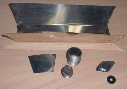
Above, the large piece of stainless sheet metal I bought from Harbor Freight as a drywall mud carrier for 3 bucks. I measured it at .0125 thick. I cut off the ends of it to use as test pieces, one of which is on the lower left This leaves plenty for the rest of the shields, or other stainless brackets that might be needed on the firewall. This stuff is much tougher to cut than aluminum!
I then bought the two pipe fittings in the center of the picture (2 bucks for both) - a pipe nipple 1 1/2 inch ID and the pipe plug 1 3/8 inch OD. I drew circles in the middle of one of the end pieces to help center the pipes, and then put it between the two centered pipe pieces, all in a vise and closed the jaws. This made an impression in the metal just deep enough that fits the thickness of the grommets. There is wrinkling around the impression, slightly noticeable in the above photo, but I was able to beat it pretty flat around the edges. I then trimmed the sheet metal in the shape of the regular shield, and its ready for drilling the mounting holes and pass through. This method does require a strong vise, though. If you had a press, that would work as well.
Firewall shields can be bought for 5-7 bucks apiece, so we're not talking about saving much money, but I was curious about working with stainless steel, so I gave it a try. Took me about 45 minutes, including the photo and this writeup.
April 12, 2002
I think I've made up my mind about the engine. It will be an XP-360 with 9:1 compression cylinders, a B&C Alternator, Lightspeed Engineering's electronic ignition, and everything else, like the baffles, mount, and cowl the regular ones from Zenith. From an auction of parts from an RV I got a 2 year old B&C 60 amp alternator:
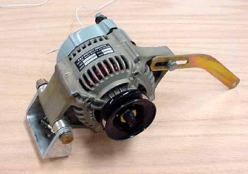
Ball bearings and solid castings. It is made by Nippon Denso, and looks great with only a few hundred hours on it. Now that I know what engine, the next step is to complete the firewall to accommodate the Dynafocal mount.
August, 2002
I did it! I ordered an Eagle IV - EX engine from America's Aircraft Engines, which is a O-360 clone. They were good enough to offer me their Oshkosh show special pricing. There are several manufacturers (parts dealers, really) who are OEM'ing the Superior XP-360 parts, putting their name on it, and assembling it and handling the warranty. They will do a professional assembly job with my ignition options and a Precision carb, and put it on a test stand and run it through a battery of tests.
Also, I picked up the ZAC engine mount for the 360:

The Type 1 Dynafocal engine mount is in position over the firewall to see how the bolt holes line up. This picture is taken pretty much dead on, and all the centerlines are lined up and plumb. However, the bolt holes didn't line up with the factory predrilled holes. I told ZAC about this, and they sent me a new one:
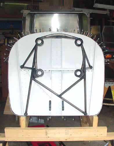
This one fits much better and the framing is a bit stronger. Note how the rear of the engine is mounted slightly off center, to the left (from the pilot's POV.) This is done so that the nose of the prop will still be centered, but the thrust line will provide a slight right turn tendency (from the pilot's POV) to help counteract the natural left turning tendencies of the airplane.
September 17, 2002
Picked up the engine today - trip report here.
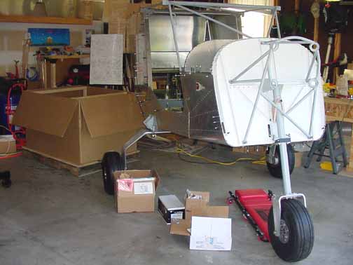
And here it is, resting safely on the floor, ready to be prepped for hanging on the mount. The boxes in front (from left to right) which were inside the main box are the front ring gear, the starter, the carburetor, and the rest of the Lightspeed ignition unit. Another big milestone!
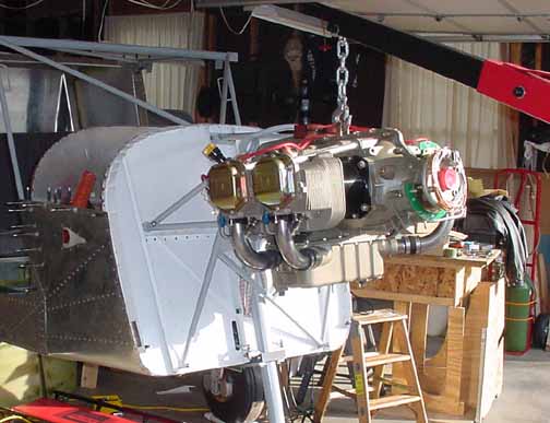
Here, the engine is resting just in front of where it will be attached to the mount. You can see the green Lightspeed ignition timing sensor mounted just behind the prop hub. You can either get it this way, or you can get a sensor that mounts where the left magneto would go. This way there are no moving parts to be serviced for the ignition, except the right mag. I needed to hang the engine to take some measurements for exhaust and hose distances so that I could get some things on order. Looks like plenty of room under the engine! Before hanging the engine, though, I need to do more prep on the firewall.
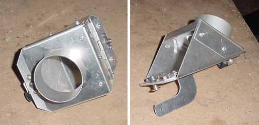
Above is the cabin heat door, a kit from Van's for $30. Took about an hour to assemble. You will need a dimple die for use with your hand held rivter because the flat side goes against the firewall and must be flush. It comes complete with clamp for the control cable and mounting hardware. It also comes with solid rivets, but I used the Avdel rivets. A 2 inch SCAT tube goes from here to the exhaust muff, which is driven by intake air from around the prop inlet. The arm on the bottom right is controlled by a simple Bowden type cable from the instrument panel, and either vents the heated air inside, or it vented down to the bottom of the cowl.
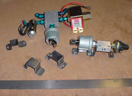
Above are some of the firewall plumbing pieces. The oblong assembly on the right is where the other end of the oil pressure line goes to. It is a 3 port manifold, with a oil pressure sensor on the left, and a oil pressure switch in the right. The switch will independently turn on and off the Hobbs meter, so the clock will be running if and only if the engine is. In the middle of this fitting is the port for another 45 non-restrictor elbow to connect the hose to. Underneath are some support brackets I made to mount these. The oil pressure sensor will be clamped to the support bracket under it with a hose clamp.
The brackets are made from some .025 4130 steel in a 1 inch strip shown along the bottom. Likewise, I've made more brackets to support the 5 port fuel manifold and its pieces. Also, I've powder coated the brackets to prevent them from rusting. On the right of the 5 port manifold is the boost pump, on the bottom is the fuel pressure sensor, to the left is the primer solenoid (I'm not going to use a manual primer - saves running fuel lines into the cabin and back out.) The boost pump and primer will be wired off the same switch - down will be off, the middle position will be for the boost pump on, and the upper position is spring loaded (momentary) and turns on both the boost pump and the primer valve. This is essentially the same plumbing as the ZAC manifold, except I am using an electric primer.
The top two fittings are for hoses that connect from the fuel pump and the other one goes to the fuel flow sensor. Originally, I was going to just connect the fuel flow sensor into the manifold, but I found out those sensors must not be mounted near any bends in the flow, or inaccurate readings can result. From the sensor, a hose will go to the carb.
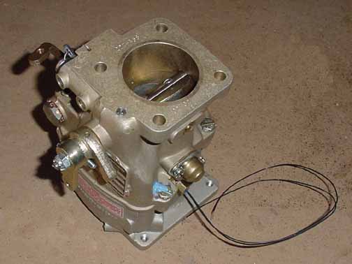
Above is the Precision (Marvel-Schebler MA-4-5 clone) carburetor. There is a bracket needed to hold the cable sheaths for the throttle and mixture controls. The top surface bolts onto the engine intake, the bottom attaches to the air box. The wire is from a temperature sensor I added by drilling out a plug on the side of the carburetor, and tapping 1/4-28. This way, if the temp in the throat nears icing conditions, I should hear a tone in my headphones, and be able to see the carb temperature on the engine monitor. Thus I can control just how much carb heat is needed.
![]()
![]()
Images on this website are either Copyright Zenith Aircraft Company and used by permission or are copyright Gary Liming