

Engine 2nd Page
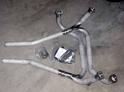
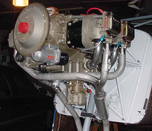
Above is the Vetterman crossover exhaust. It is all stainless steel, and has some of the best welding I've seen, stainless or not. The shiny spot in the middle are the ball sockets that fit perfectly and allow the tailpipes to be positioned in a variety of ways. Although this is made for a Glastar with an O-360, I m hoping it will fit within the cowl. The carb heat and cabin heat muffs aren't shown. The Vetterman kit comes with a cabin heat muff, and I need to get a carb heat muff.
December 12, 2002
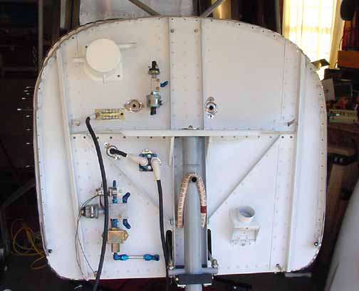
Here, I've prepped the firewall about as much as I can before mounting the engine. On the upper left, I've powder coated the oil separator and mounted it. They don't have one on the demo 801 at ZAC, and the belly looks like exhaust all the time. Since mine is going to be mostly white, I want to reduce the residue. The right hand inlet is from the engine, and the left hand one will go down to the bottom cowl for the air to flow overboard. The bottom small outlet is for the recovered oil to go back to the engine. Just under it I've mounted the oil pressure manifold with the pressure sensor and switch. Next to it is one of my homemade firewall shields with a grommet for some wires to pass through. The brass colored strip is a common ground with many tabs to easily connect devices to ground. There is another larger strip on the opposite side. The black 2 AWG welding cable from it will go to the engine block. There is one on the other side which goes to the battery.
Just under that is the starter contactor, which has one 2 AWG wire going through the firewall to the battery contactor, and the other one will be connected to the starter. Just below that is the fuel manifold, which has the fuel pressure sensor, primer valve, and boost pump. The fitting just next to the steering rod goes to the engine fuel pump, and the two AN fittings off the manifold are for lines from the engine fuel pump, and out to the carburetor. I will add a stainless cover for this plumbing later, like they do on some Pipers.
To the right, I've powder coated and mounted the cabin heat box, and I've added another firewall grommet and shield for engine sensor wires. I haven't drilled for the control cables yet because I am not sure where I want them, or how big a hole I will need. Lots of room on this firewall.
Here, the engine is officially hung! The bolts and motor mounts went on fairly easily. The forward end of the bolts have the nuts on them that are difficult to get to. I've also added the exhaust, which took only 10 minutes to attach and fit perfectly. However, these exhaust tubes are long, allowing me to trim the bottoms to just peek out of the bottom of the cowl.
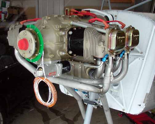
I will trim them level with the bottom of the fuselage, sticking out about half an inch, and I need to attach the hangers as well. I've also bolted the starter on.
Here the flywheel is on and the alternator is mounted, and uses a Gates 7365 belt as per the folks at B&C. The last few digits represent the circumference of the belt, so a different size pulley would need a different belt number. The cabin heat muff (Rick Robbins's work) is installed, as shown in the lower right, and all that is left for it is the SCAT tubing to the firewall heat box. The inlet air will come from a flange off of the rear baffle. Also, Robbin's carb heat muff is mounted on the aft crossover exhaust, which you can see peeking down. It only needs SCAT tubing down to the carb heat box (not mounted yet.) It also serves as an alternate air source for the engine should the front air opening in the cowl ice over. If that cabin heat muff isn't enough, its is nice to know that it looks like there may be room on the other side for another one. I need to trim the pipes and add the EGT probes, and the exhaust will be done.
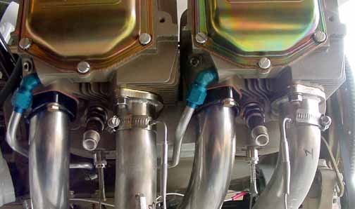
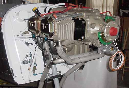
The picture above was taken from the starboard (right) side of the engine looking up a bit. The exhaust gas temp probes have been installed with hose clamps on the exhaust. Its not really important where they go on the pipe as long as they are all the same distance down from the cylinder, and you can position them for easy access and clearance for the cowl. The cylinder head temp probes are also in place using a bayonet type attachment that attaches into blind holes under the cylinder. These are visible just under the spark plugs. I don't have the lower magneto driven spark plug wires on yet because the engine and ignition switch aren't grounded yet.
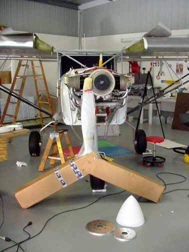
My prop has arrived! It is a 3 bladed, 70 inch diameter, 54 inch pitch composite prop from Catto Props. Why this one? Long story, but first I suggest anyone getting a prop talk to the big prop makers as much as you can, especially the wood prop guys in the Florida branch of Sensenich. It is an education trying to properly fit a prop to the airframe and engine. DO NOT wait until everything else is done and then go out an buy a prop. Start talking to these guys as soon (if not before) as you make your engine choice. I wanted a wooden prop because 1) they are lighter 2) they disintegrate on a prop strike, instead of ruining the engine, and 3) they don't have harmonic ranges to avoid like metal ones. The disadvantage of wooden ones are 1) they are usually less efficient because you can't get thin edges on them like metal ones and 2) they aren't as durable. I went with the one above because being a composite (its a wood core with a fiberglass coating that can get an efficient feathered edge) it should be reasonably durable. Craig Catto mostly makes aerobatic props for RV's. I chose the 3 bladed variety because Sensenich (and Catto) said for this engine/airframe paring, I should need a 80 inch prop. (A metal one doesn't have to be as long.) At 80 inches out there, the tips start to approach the sound barrier, so they get quite loud. This one should move more air and be much quieter. I am going to leave the prop in the box until I am ready to mount it.
Also, shown above on the starter ring is a 2 1/2 inch prop extension (Van's) for the prop to bolt onto, and I also bought Van's spinner kit, shown on the floor in front of the prop. It has a rear and forward flange, and the fiberglass work is flawless.
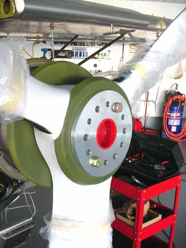
Here, the prop is temporarily mounted to fit the spinner. The mounting order (from the engine flange out) is starter ring, prop extension, rear spinner bulkhead, prop, front spinner bulkhead (you'll have to trim it a bit to fit over the prop necks) and then the crush plate. I think it looks great!
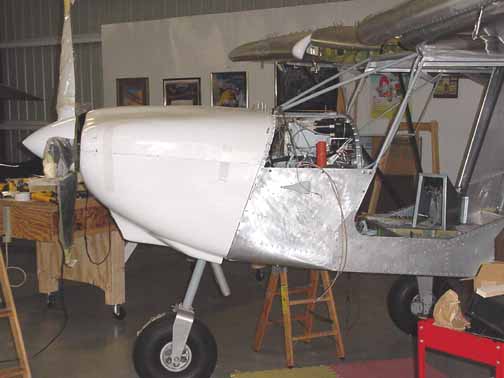
Now the top cowl has been fitted and cleco'd in place and the bottom cowl has been trimmed as per the manual and is held in place with tape. The fit isn't as bad as I thought it would be. I have also started to cut out the slots on the spinner - you just have to cut a little bit, and fit, mark it, cut a little bit, until a good fit is achieved.
![]()
![]()
Images on this website are either Copyright Zenith Aircraft Company and used by permission or are copyright Gary Liming