

Engine 3rd Page
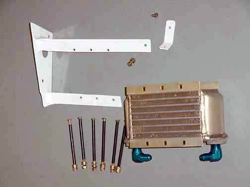
The oil cooler bracket that was supplied by ZAC didn't fit, despite the similar dimensions of the engine, so I cut out the 4130 and drilled it after making templates, and then had it TIG welded and powder coated. Here are the parts ready to mount.
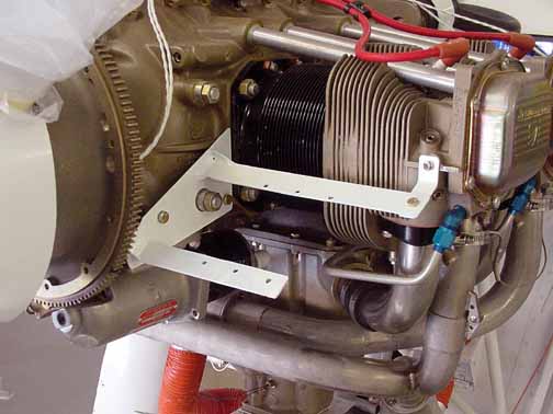
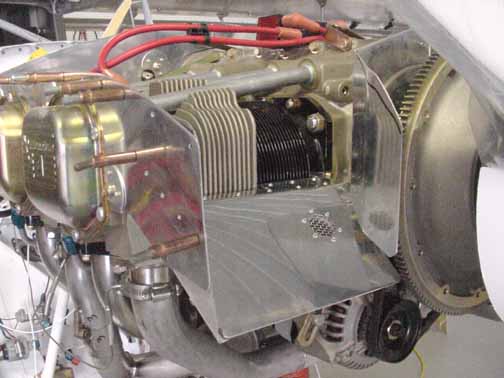
Here is the oil cooler bracket in place, ready to accept the bolts for the oil cooler. Note the engine case bolt that protrudes through the bracket. This will be covered with baffle to direct the air down through the cooler.
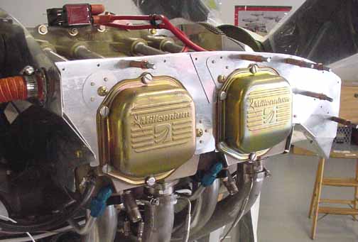
Here is the baffle kit from Van's for the O-360. It comes with very snug fitting baffles around the engine, and you have to cut it down to leave about 1/2 inch gap between the baffle tops and the cowl when in place. This gap will be filled with a baffle flap to form an airtight seal that forces air from the front down around the cylinder fins.

Here is the baffle around the oil cooler and on the left side of the engine.
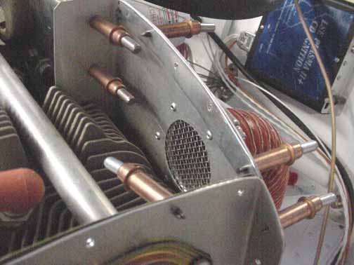
Here I've cut a hole in the rear left of the baffle for air intake to the cabin heater. I read once about a guy whose cowl sucked in a bee and it traveled trough the heater right into the cabin, making for an interesting departure. I've added a stainless steel screen as I've seen done by ZAC and on some other production aircraft. I got it from McMaster-Carr and it is sandwiched between the baffle and a 2 inch flange (not supplied.)
Here is the right side - I added another screened vent on the scoop to cool the alternator. I still need to add some angles to fill the gap on the front baffle. I also added a screened 1 inch hole on the rear of the right baffle to cool the magneto, seen the previous photo of the right side. The opening for the carb heat still needs to be added.
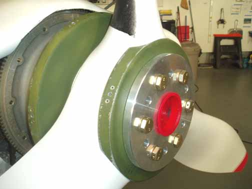
Here, the spinner has been drilled through to the bulkheads - how I did this was a bit complicated - I cut out the openings for the prop blades a little bit at a time until a good fit was achieved with a slight gap for blade movement. Then, I placed the spinner on the bulkheads in what I thought looked "pretty close" to the spinner being perfectly centered, and drilled one hole and clecoed it in place, and used clamps elsewhere. Then, I had a friend hit the starter switch and watched the spinner nose while the prop turned, adjusting the spinner position until there was zero wobble of the nose. I then drilled more holes, checking for wobble after each hole. Then nutplates were installed at each hole as shown above.
Also, the prop bolts have been installed, torqueing them initially to 25 ft lbs, and then, going in a criss-cross pattern, torqueing each bolt with an additional 5 ft lbs until 45 ft lbs was reached. I will wait a few weeks, and recheck the torque of the bolts until there is no movement needed, and then safety wire the bolt heads as per AC 43.13.
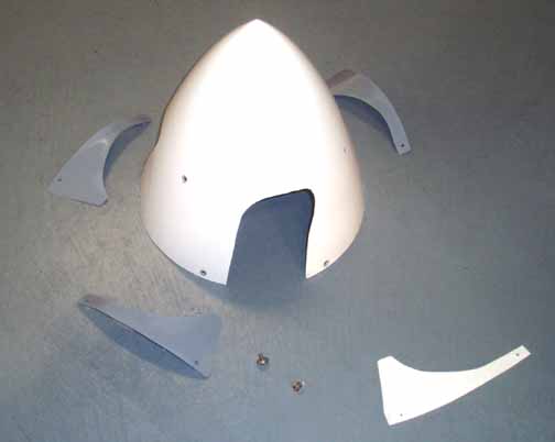
Here is a picture of the trimmed, drilled and countersunk spinner. I also cut out a template to cover the gap behind each blade, shown by the white cardboard in the lower right corner. These gap covers are shown with a coat of primer around the spinner.
![]()
![]()
Images on this website are either Copyright Zenith Aircraft Company and used by permission or are copyright Gary Liming