

Final Assembly Page 2

Here, the tail is pretty much done. The trim tab is just clecoed in position, along with its cover. The flight controls are all in and the cables have been swaged, and the stops are in place using the templates shown in the drawings. One bit of advice - the lower fin (the part that rivets against the fuselage top skin) can be drilled and clecoed. Then, before cutting the upper fin (the part that rivets against the top of the horizontal stabilizer) use some poster cardboard and cut a template. You should end up with a much better fit. Especially wait until the bottom edge is in place to measure and cut the gap under the front of the rudder.

Here, I've added a little extra fairing that extends the aft edge of the lower fin back to the aft horizontal stabilizer attachment. I thought long and hard about making some kind of fairing to cover that front attachment point, but nothing I could think of would be less drag.

Here is the way I attached the rudder cables to the pedals - rather just connect the cables directly to the pedals, I let the turnbuckles back at the rudder all the way out, and made up the cables to fall short of the pedals by 2 inches. I then made a pair of links of 4130 steel about 2 inches long and drilled them to AN3 holes on each end and powder coated them. This will allow me to fix any cable stretching by just changing links, as well as providing a place for my feet to touch without touching the cables. Thanks to Jerry Erickson for this idea. Also, you can see the Yamaha snowmobile rod covers installed over the nosewheel push rods.

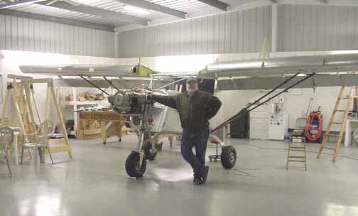
Ok, time for the wings. I've got them up on supports, with the outboard ones adjustable in order to set the dihedral. The cabin is level - you can adjust for level by inflating the tires carefully. The struts are in place and drilled - mine fit with no problem. To see the wings on is a nice milestone!
To set the dihedral, I made some 90 degree angle scrap that I clecoed to the inboard wing ribs, and cut them off exactly 148 mm high. You can see them sticking up off the wings in the above photo. I bought a laser level which makes a horizontal laser line, and raised each wingtip until the laser touched both wing tips and the tops of both 148mm angles at the same time (the laser width is about 1/8 inch.)
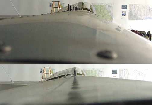
Here you see two photos, the upper one with the camera off line showing the clecoed angles (as well as the row of clecos for the upper wing skin - I still haven't riveted them, and I am still glad I haven't!) and the lower picture with the camera right down the rivet line. Also, I made sure the distances from each wing tip to the lower rudder bolt were equal. To do that, I found I had to remove about 3/8 of an inch of the rear wing spar in order to allow the wings to be straight across, perpendicular to the aircraft center line, and not swept forward.
Here, the struts are bolted and the flaps have been added and the flaperon controls in place. I need to add the jury struts and the leading edge slats and the wings will be done!
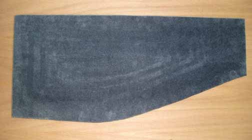
Above are some upholstered door inserts. They are made from 4 layers of corroplast (the stuff that looks like corrugated cardboard only is made of plastic) that form a concave shape, giving the panels a sculpted look. The layers of corroplast are glued together, and then the upholstery material is put on with spray headliner adhesive (sold at auto supply stores. I made two of these for both doors. The corroplast came from a local politician's campaign yard signs! They look plush. Together, both weigh 32 ounces, a bit heavy, but his will give the door a badly needed "solid" feel and make them quieter. If I ever have to worry about the weight, they are just held in place with two strips of velcro at each end.

Another finishing touch - the white pieces above are the interior door handles and the seat locking rods. They have been powder coated white, and then the grip ends have been dipped in that plastic stuff that is meant for tool handles. A bit nicer to hold onto than gripping plain steel. Follow the directions for this stuff closely. I also got them to "cure" more rapidly by putting them in the oven at 150 for 5 - 10 minutes after they stopped dripping. Also, now that the plane is almost done, I put plastic handles on my cleco pliers! (Go figure.)

Above is a lesson learned: Back some time ago, while still working on the tail, I noticed some rust appearing on the cabin frame. To stop that, I prepped the cabin frame for a coat of primer using steel wool to clean it. MISTAKE. I should have used a Scotchbrite type pad instead. What happened was that small (really small) pieces of iron from the wool imbedded in the 4130 frame, which eventually caused the rust shown above. Now, I need to sand it down completely and repaint it.
![]()
![]()
Images on this website are either copyright Gary Liming or are Copyright Zenith Aircraft Company and used by permission