

Final Assembly
October 16, 2002
Picked up the upholstery for the seats today. I had them done by Winona Drake of Drake upholstery, and she did a great job:
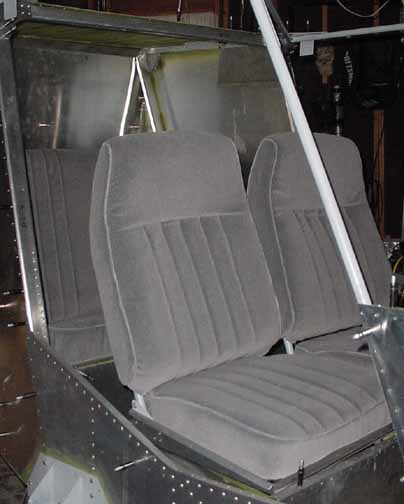
Here, the front seats are shown. A picture of the seat frames is on this page. They use the dense foam on the seats, shown here, and Drake supplied foam on the tops. The bottom seats are sculpted slightly with rises along the sides. They are held in place with velcro, and the tops slide down over the frame and are also velcro'd along the bottom. There is a lined map pocket across the back of each front seat. In this picture, the seats are just sitting on top of the seat support.
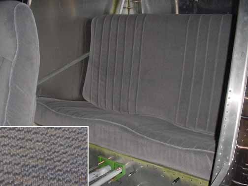
Here is the rear bench. It is all Drake supplied foam, and is sculpted for the two seating areas. They will both be velcro'd in place after the rear set assembly is riveted. They actually look better than the photo shows - the insert shows some of the color in the fabric. Drake also supplied 4 yards of matching material to cover the baggage area and all side panels.
June, 2003
Well, I took some time off of the project to get the hangar ready. Spent waaay to much time on it, but it will be worth it. (Although pretty far off topic, if you're interested, click here.)
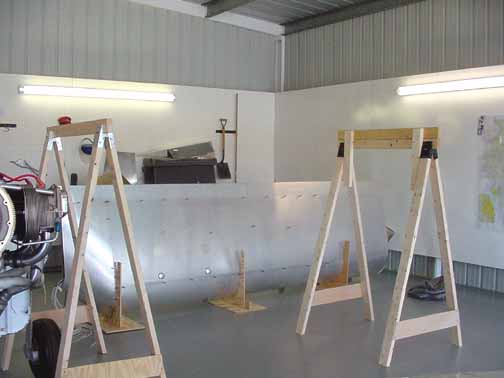
Above, you can see that I've made some wing stands - simple saw horses with the outboard ones adjustable by raising the upper horizontal 2x4, and screwing in place as needed to set the dihedral. The wings are resting in the background waiting to get the root ready to place.
I've placed the horizontal stabilizer on the tail, clamped it, and aligned it to be true to the centerline of the aircraft, and level with the reference line. Also, you can see I've installed the nylon fairlead plates for the control cables. Those attachment points sure stick down!
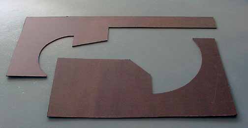
Next I've cut out the deflection templates per the drawings, the lower one for the elevator, and the upper one for the flaps.
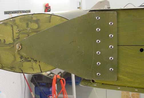
Above, I've substituted my own outboard elevator hinge - the one supplied was .032. I was concerned about the steel pin wearing on just some .032 material over time. (This is just like the oval wear pattern on the flap hinge pin on the demo 801.) I substituted some .090 6061-T6 which should provide about three times the wear resistance. There is also a nylon washer on the hinge pin between the hinge and the elevator, and I added another rivet line. All in all, just a little peace of mind for a tad under 4 ounces of weight increase for both hinges.
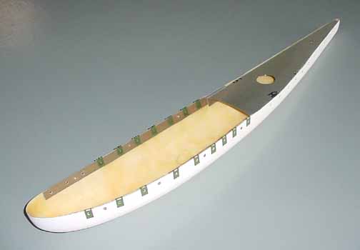
The directions just say to rivet the fiberglass stabilator tip onto the aluminum skin. I wasn't too wild about this, thinking that there should at least be an aluminum washer behind the fiberglass, but how to hold it in place while riveting blind rivets? After careful fitting of the tip in place on the stabilator, lining up the holes with the rivet line on the edge of the stabilator skin, etc. I drilled the position of each attachment hole. I then cut scrap aluminum strips, and epoxied and riveted them in place with flush rivets. I could have used nutplates here, but that would have been twice as expensive as using the 6-32 Tinnerman clips shown above. The rear aluminum insert is riveted in place normally, since the shop end of the rivet is against aluminum already.
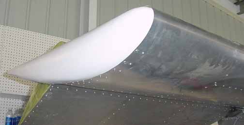
Here is the tip in place - the 6-32 screws don't look that much different than the rivet line and the Tinnerman clips do not show. Since this is a likely place for hangar rash, as well as being an inspection point for an annual, having the tips removable will make maintenance easier.
Now, I am trying to finish the tail - inside out. I am very glad I waited to rivet and put up with clecos on the top skin of the rear fuselage until now - it gives me easy access to the area shown below:
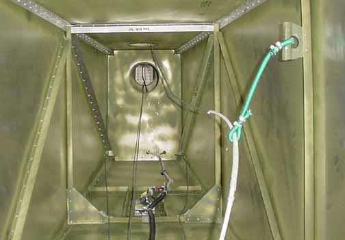
Here, you can see the elevator cables going up through the bulkhead holes, and the rudder cables going to the sides along the bottom - I haven't attached them yet. I made some gussets to support the "L" stiffeners, and put some nylon plate under the area where the cables will go. The wires from the aft bulkhead are the tail light wires (white) and the rudder trim wires (gray.) In the middle is the tail camera fixture in place, shown here. All these wires get tucked into some black split tubing. The nylon clamps are riveted to some standoffs I made from some scrap .025 that resemble a "P" when seen from the side. After the top skin is in place, I will add gussets to the top corners. They weigh 0.5 ounces.
Also shown is the bungee cord to keep the crossed elevator cables from rubbing. When the cables are installed, they will be taught, instead of slack as in the photo. The bungee arrangement is a bracket I made by rolling the edge of a piece of scrap around a mandrel, and using the step drill to cut out and file a hole. This was riveted to the side "L". The cable was covered with a split white cable sleeve sold at a boating supply store (West Marine) just for 1/8 inch cable. I added some spiral wrap, and the bungee is attached with a crimped metal Romex staple and some wire ties.
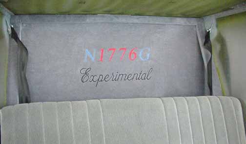
Although it may seem I'm getting ahead of myself, I went ahead and put on the upholstery in the baggage area because its a lot easier to get to this area with the top skin off than on. Also, I installed the rear seat belts for the same reason. The side panels will wait for the windows. Here, the top skin has been put back on. I had the registration number embroidered, as well as the regulation 2" Experimental notice.
![]()
![]()
Images on this website are either copyright Gary Liming or are Copyright Zenith Aircraft Company and used by permission