

Fuselage - 3rd Page
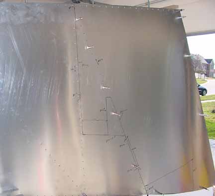
The next step is to place the top skin, but it looks like it will be much easier to put the COM antenna mount on now, rather than from a ladder later on. (See antenna description on Avionics page.) At Wings of Hope, I saw some planes where the antenna had dented the skin slightly. I don't think it was wind resistance that did it, but it did look like a little reinforcement would have helped, so I made a doubler out of some scrap .025:
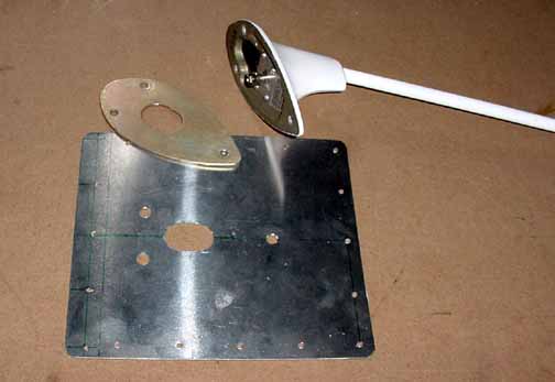
And this was riveted underneath the top skin, and the mounting holes drilled and all ready to bolt the antenna on at final assembly.
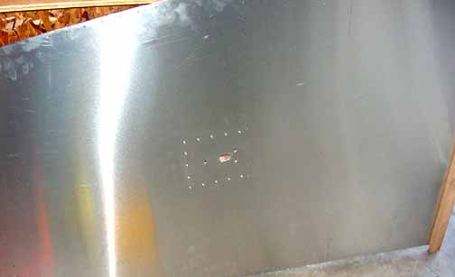
The front edge of the doubler is riveted with the std L that goes across the fuse at that point. Here, the skin is ready to lift onto the top of the fuse, but I think I need to get some help for that.
Okay, the top skin slid into place under the jig, and HT frames are all drilled, along with the Horizontal Stabilizer mounting brackets and rudder hinge mounting brackets. When it is all cleco'd together, it is interesting how rather floppy sides and very thin parts come together to make a very stout structural integrity. Tensegrity, I think Buckminster Fuller called it.
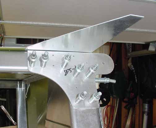
The mounting brackets above are held in place with some AN3 bolts. I looked everywhere, but I could find any in the kit. I called ZAC, and they said the AN hardware comes with controls kit. Makes sense, but this is the first time the manual called for something that wasn't in the sub kits. If you bought the whole kit package at once, then you should have everything. Otherwise, save yourself the searching, they will come later. I just used some 10-32 hardware store bolts to hold them in place for now.
It has all remained right on square. All that is left to do here is open up the holes to their final diameter. Since riveting it now would mean the fuselage is permanently put together, and since it now takes up my entire workbench, I will wait to rivet! The manual doesn't say, but here is where you drill the hole for the tie down ring, centered 10 mm from the rear edge of the bottom rudder hinge bracket.
On to the front of the rear fuselage.
The best way to keep the front true is to clamp a straight board across the top, hang a plumb bob from the centerline of the top skin, and clamp the plywood template in place to keep the sides square while working on it.
I found it helped to mark out on the side where all of the pieces will go, like they did in the manual.
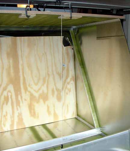
Then, start adding the support structure for the rear seat and baggage area. A word of advice here - the bottom skin is very thin, the thinnest sheet metal anywhere on the plane. I accidentally dropped the cleco pliers while working in this area, which made a small ding on the bottom skin. I smoothed it out with a spoon, but it is a good idea to put a layer of cardboard over the bottom, maybe with a towel over it to prevent that. (Not pictured above.)
April 12, 2002
I just got back from Sun N Fun, and learned a lot about some choices I need to make. When you get to this point, you have to start thinking about engines and the panel, so going to Sun N Fun or OshKosh is well worth your time at this stage.
When I got back, I found that the boys at Zenith had re-written the fuselage assembly manuals, along with several measured drawings. They are *much* better. I really appreciate the measured drawings. Hooray!!!
Next, the front braces are installed. In the picture below, the plumb line is off center to make room to work. It was reset and trueness was measured when drilling the wing attachment brackets.
The top brace is the new part that was mentioned in the newsletter. This is the brace that connects the rear wing attachment points. The thickness of the part now matches the side braces, but is is not as wide, as you can see below. Take your time here and make sure you cut the 45 degree (well, 46 degree) angles several mm long, and use a sander to creep up on the right length.
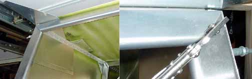
Then, on both sides, drill the wing attachment bracket, while making sure the fuse is held square and the wing bolt hole is the specified distance (586mm) from the centerline.
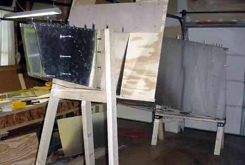
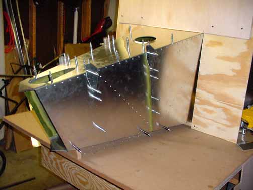
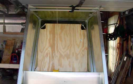
According to the revised manual, plans are provided for a rear wooden frame to hold the fuselage the correct height relative to the front when the time comes to mate the front and back. I went ahead and made the frames, with the front just resting on one of the sawhorses for now. This will make it easier to finish the rear seat baggage area, and leave the table open to construct the front fuselage section and the firewall. I left the square jig around the rear just to help hold the fuselage square while moving it and working on it.
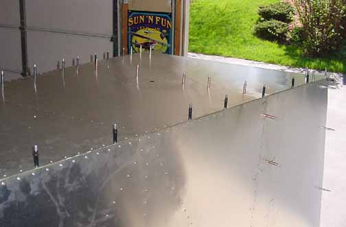
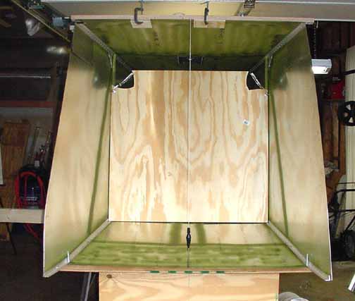
View from the top - the front splice plates are just pilot drilled (silver clecos), the top of the baggage back and the top stiffener is drilled A4 (copper clecos) and the sides are drilled A5 (black clecos.)
![]()
![]()
Images on this website are either Copyright Zenith Aircraft Company and used by permission or are copyright Gary Liming