

Fuselage - 4th Page
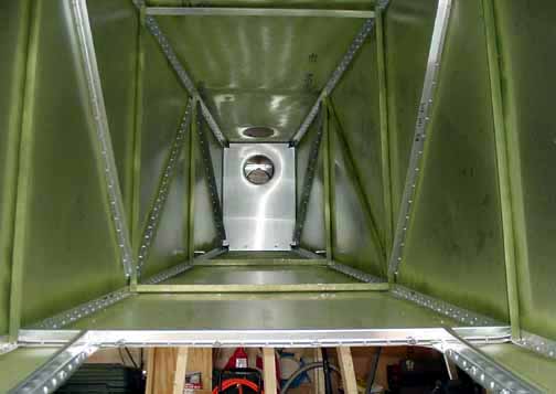
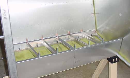
View from the inside. The camera was off-axis a bit, so there is a bit of the fish-eye effect here. Other than the skin "L's", the fuselage is only cleco'd together at this point - two of the top "L" stiffeners are not in place. The top skin has some large open areas. I was thinking of putting a couple of "L" s in diagonal between the top "L"s to reduce the "oil can" popping sound I've heard in the demo plane, but that is easy to add later so I will wait to see how much of a problem it is.
Here, the baggage back has been cleco'd in place, drilled through the top and side stiffeners.
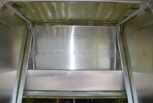
Next, the baggage floor is drilled, primed and cleco'd. To it, the stiffener across the bottom is added and also two "Ls" parallel to the sides that support the control brackets installed later. Then, the baggage front is added. The seat back is next, attached to the top of the baggage front, and the stiffener that was just added.
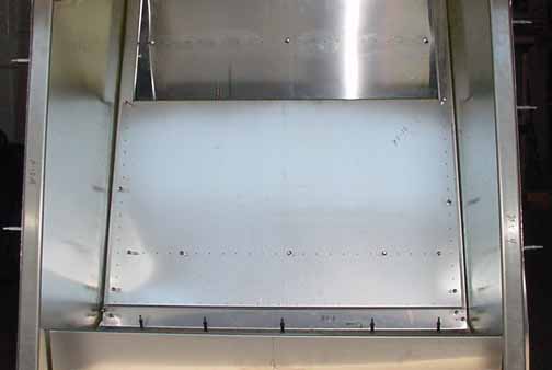
Here, the seat back is on, attached across the top to the baggage front, down the sides, a stiffener added across the middle, and along the bottom. At this point I am getting really thin on clecos, especially the black ones, as very little is riveted at this point.
Another of the stiffeners is in place behind the seat back, shown by the line of rivets at the top of the above photo. Here the seat stiffeners are cleco'd in place. They got there by fitting them to the seat top (not shown - lining up the rivet lines through the predrilled holes in the seat) drilling them, and then transferring them to the drilled holes in the seat supports. Now they get "L's" on each end, as well as all the metal that butts up against the skin needs to have "L's" fitted and drilled.
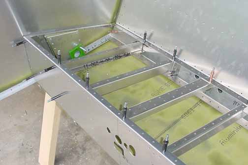
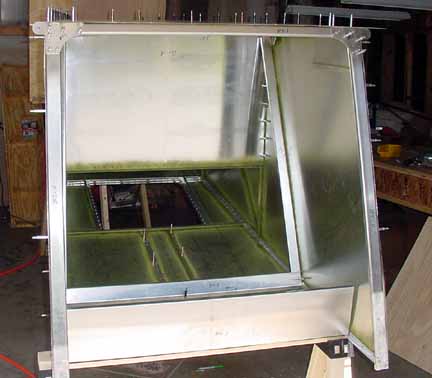
Each cross piece has had the "L" supports added, the front and rear seat supports have been drilled out according to the new drawings to accommodate the control tubes and cables, and I've added the flaperon control tube supports (the boxes with the green bearings) on either side of the seat. Doesn't look like much has happened since the last photo, but actually quite a bit of work has been done.
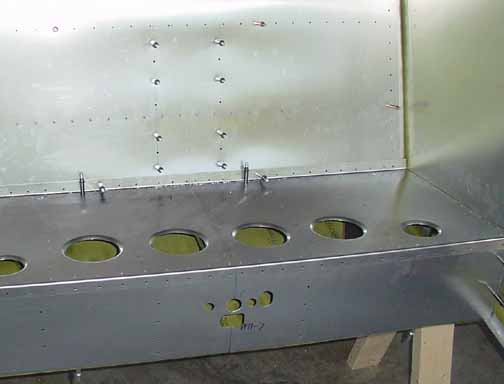
Here, the seat back is in place and drilled and cleco'd into the bellcrank supports behind it.
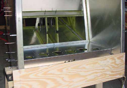
This shows the bellcrank supports behind the seat, the steel and primed center seat belt bracket in place, and a rear fuselage opening template clamped in place to mark for a cut to fit. The bellcrank will be installed with the rest of the controls. With that, the rear fuselage is completed, and on to the forward cabin, starting with the firewall.
![]()
![]()
Images on this website are either Copyright Zenith Aircraft Company and used by permission or are copyright Gary Liming