

Fuselage - 2nd Page
January 26, 2002
The right side went quickly.
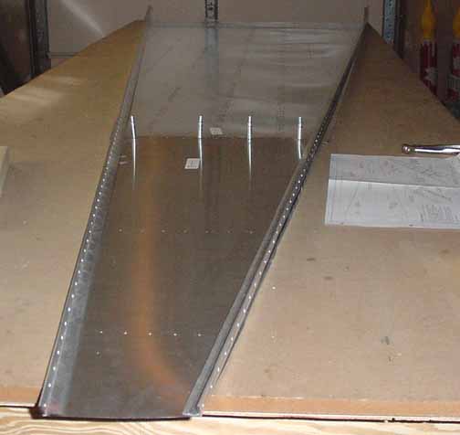
The next step is the bottom. Here, just like the sides, the first procedure is to rough cut (within 5-6 mm) the skins, and lay the two pieces with enough overlap so the total length is what the drawing says it should be. Then the overlap is marked, trimmed, and drilled. Above shows the skin inside up, with the longerons (which already have the sides drilled out for the sides) sitting like they will eventually go. The bottom skin is only .016 thick, so it is very fragile. I believe this is the only place in the aircraft that uses this thickness. I hope the landing gear doesn't kick up a rock, or there will be a ding for sure. Next, the skin will be turned over, and the "L"'s and "Z"'s laid under it to be drilled and cleco'd.
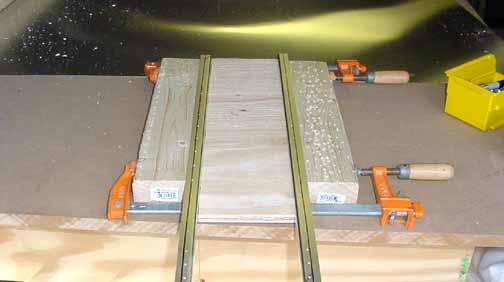
Here is the 120mm jig spacer clamped with the "L"'s ready to slide under the skin and be drilled. (The skin is outside up.) The manual has you put these in later, but it sure looks much easier to do it now. Once all the "L"'s, "Z"'s and longerons have been drilled along the predrilled holes, it will be flipped over for trimming. Save this spacer, it is also used later.
Here is the bottom skin with all the "L";s, "Z"'s, and longerons drilled, cleco'd and trimmed. The skin has also been ground to the final fit with the drum sander - it is much easier to grind .016!
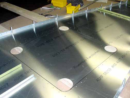
The door access was cut with four 3 inch circles in the corners, and the Jilson tool made short work of cutting along the outer edges. Next, the door panel is cut to size, and nutplates are installed around the door opening.
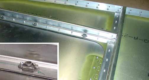
Above shows a corner of the door where the "Z" is riveted to the skin, and a few spaced nutplates are riveted as well. These allow the access door to be screwed into place. The door is riveted onto piano hinge, which is riveted between the forward "Z" and the skin.
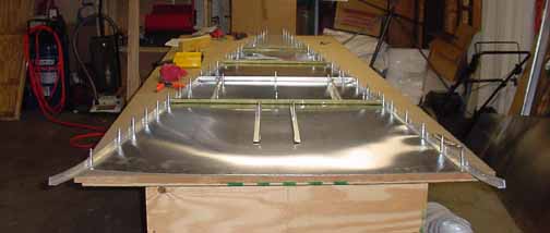
Here is the finished bottom, longerons, "Z"'s, and "L"'s all deburred, primed, and riveted. The two parallel "L"s in front are just cleco'd in place at this point. The drawing shows another piece, the rudder control cable support riveted onto the upright "L" just aft of the door. I didn't have one in my kit, so I guess it comes with the control cable kit. Sure does seem like it would be easier to drill and cleco in place now, though.
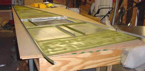
Above, the top skin is trimmed and drilled with the "L"'s, longerons, and gussets - they're under there. Next it will be primed, but not riveted until the whole fuse is clamped together. The longerons are riveted to the side skin. Also above you see something that has helped in doing these skins - I printed eight of the measured drawings and taped them to a poster board and placed it on an easel. Makes easy reference about where things go and what's next.
The next step is to put the sides together, true up the angles, and put in the rear braces. The manual emphasizes the need for square sides while doing the final drilling. This calls for a template:
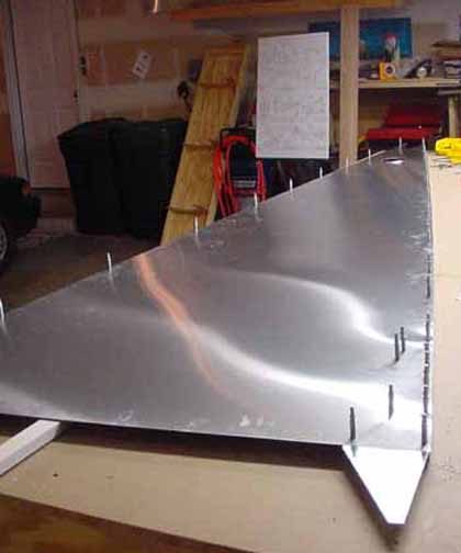
The template I cut from a 4x4 sheet of 1/4 inch plywood. The sides are as square as I can make them - I took the opportunity to re-align my table saw when I cut them. To do this, I purchased a new 24 inch steel square for 5 bucks at the hardware store. Beware - even though the one I got was a new Stanley, it was not quite exactly square. Simply dropping those just right can throw them off. I measured it with the "flip scribe" test, and found it needed a slight adjustment. Once true, I used it to align the blade and table saw fence. Although the above photo makes things look a little off, I think it is due to the slight wide angle effect of the camera lens. Everything is square on that end.
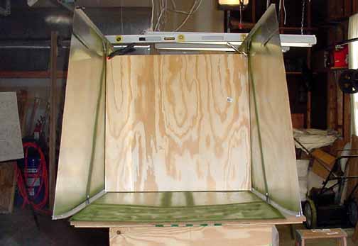
The aft end needs to be held square while the HT frames are drilled in place. The manual shows just holding a square up to both sides, but the whole thing kept moving around while trying to get the HT frame in place, so I made a jig. Since I had some 10-12 inch wide pieces of plywood left over from cutting the template in the previous picture, I used them with another piece of scrap I had. Although not easily seen from the above pictures, I have the whole fuse sitting on some 1x2s laid flat and perpendicular to the fuse, like they show in the manual.
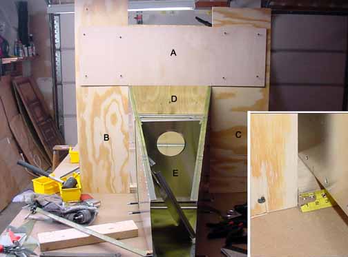
To make the jig, I first measured forward 100 mm from the aft end of the upper longerons, and placed a mark on the top of both longerons at that spot. I then dropped the square straight down from that point to the table, and marked and placed the 1x2 so that it was directly below where the 100 mm mark was on both sides. Then, I laid the scrap piece marked A across the top at the 100mm marks, and marked on A where both of the side skin edges fell. Then, I stood piece B up from the table and marked where the top of the upper longeron fell on it. I removed them and placed piece A over B and used the square to make sure they were true, and screwed them in place with four drywall screws. Then I did the same for piece C, also making sure the A-C corner was also square. When the jig is placed over the fuse, you can move the fuse walls so that the gap at the bottom between the jig and the skin, as shown in the insert, is equal on both sides. (Mine was 18 mm.) Then, screw the bottom of B and C into the 1x2 resting on the table, and the rear of the fuse will be held true and square. If you want, you can also screw the 1x2 into the table top, but I didn't find it necessary. Also, if you still find the sides moving around while fitting the HT frames, you could take some wedges and gently drive them into the gap on both sides to keep them equal, but I didn't need that, either.
All that took less than 5 minutes - it is harder to explain than do. To clarify the picture, the area marked D is just the front template, and is not part of the rear jig. Also, the forward HT brace marked E is just sitting in place, a little off axis, and has not been squared or drilled yet. The rear one is just leaning against the side, waiting its turn. Forgive the clutter on the workbench, I forgot to clear it before taking the picture. With the jig in place, it was easy to drill both of the HT frames in place while keeping the fuse quite square.
![]()
![]()
Images on this website are either Copyright Zenith Aircraft Company and used by permission or are copyright Gary Liming