

Fuselage - 5th Page
April 19, 2002
Started the front fuselage with the firewall. You start with a galvanized steel blank, and add the stiffeners and brackets until it looks like this, as viewed from the engine side:
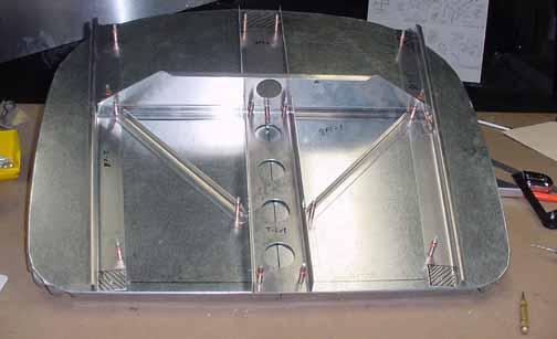
Here, most of the structures are on, cleco'd, and await laying out and drilling the rest of all the rivets for each structure.
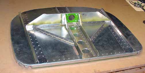
Here is the completed firewall, primed (in between touching pieces), riveted, and ready to be painted. The elongated hole (there are two of them, one is hidden) near the bottom is for the steering rod to pass through. The green plastic is the top nose strut bearing.
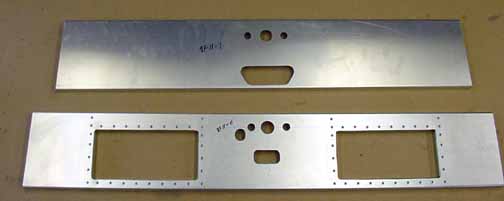
Next, the front and rear supports for the front seat are pre-drilled like what was done for the rear seat. There is an option to create an opening under the front seats to allow rear seat passengers to slip their feet in, effectively giving them more foot room back there. It involves simply cutting the opening and riveting "L's" around it, which was done in the above. (I later discovered a mistake in the above - you should wait to drill and rivet the top corner and topmost rivets in the above two openings until you fit the seat top in place. I had to drill them out while fitting the seat top. No big deal, but you should wait to do those holes.)
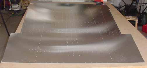
The above pre-drilled cabin floor has been trimmed and is ready to bend. It is symmetric from left to right, so it has no up or down until you bend it. It is shown with the forward edge at the bottom of the photo.
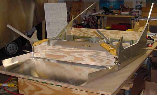
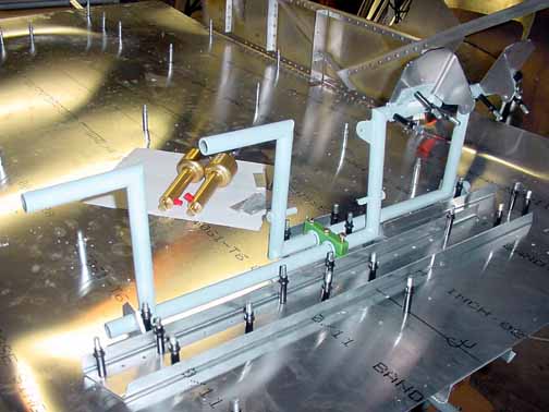
Here, the slots on the sides have been trimmed to accurately position the side assemblies, the skins bent, centerlines drawn, and the plywood templates have been cut and clamped in place. Also, the front, rear and center supports for the front seat are checked for proper positioning.
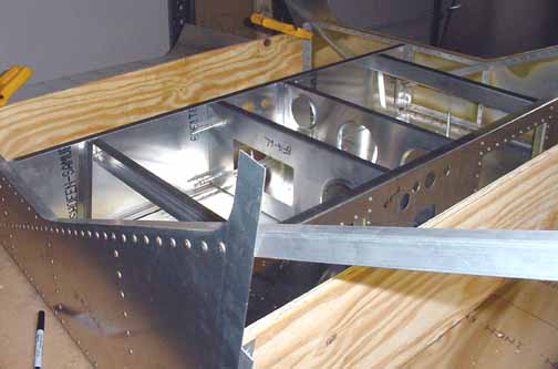
Here, more detail of the front seat supports. Each of the cross pieces have "L's" to be cut and placed, and the top of the seat has to be cut and fitted.
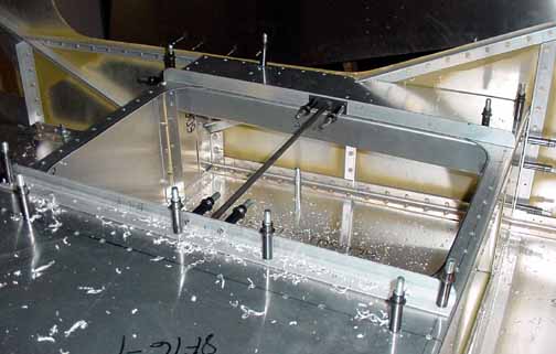
Here, the seat top has had the holes cut in them and it has been fitted onto the seat supports. The passenger chair rails are in place and the supports (with "L's") have been drilled out. Lots of drilling. Need to deburr and prime all these areas. The battery and ELT will probably go in this section.
Above the flap actuator motor is installed - the motor is under the pilot's seat, and the actuator is between the seats. The clamped piece is a steel bracket. I've put the actuator rod (it still has the tag on it) on for a trial fit through the rear seat panel hole. It seems to line up pretty well, as shown below. There is a plastic bearing for the rod to be installed yet.
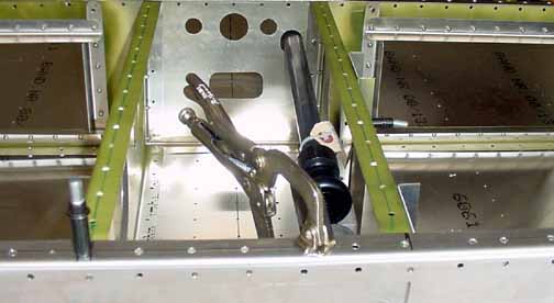
One thing you may notice - the "L" supports around the foot hole openings are riveted. You learn to delay riveting anything as long as you can, but unless you have an infinite supply of clecoes, you rivet things that look like they won't be in the way later. In this case, I should have waited because it would have been easier if those "L's" weren't there yet.
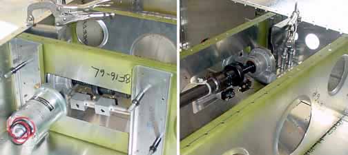
In the above picture the seat has been removed, and the rudder pedal assembly has been installed. The brake pedals for the pilot side are drilled and cleco'd. Since the pedals and hinges are steel, they are primed. Everything else is just cleco'd in place. The hydraulic cylinders and their brackets await their turn for the drill.
![]()
![]()
Images on this website are either Copyright Zenith Aircraft Company and used by permission or are copyright Gary Liming