

Fuselage - 6th Page
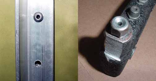
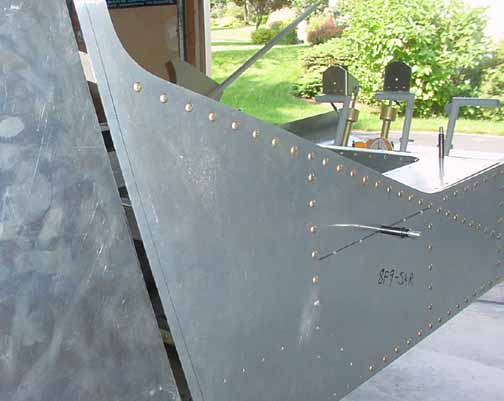
There are longerons and a wide stiffener that is riveted to the bottom exterior of the floor skin. The wide stiffener is no problem, but I ran into a problem on the longerons. When I marked the centerline down the length of both longerons, I marked the center of it using the whole width of the longeron, just like before. This gave me a rivet spacing as shown in the left hand photo above, with the rivet hole too close to the upright part of the "L." What I should have done is marked a centerline using just the open area of the longeron. (Previously, all the longeron riveting has been done from the flat side of the longeron.) The holes forced the head of the rivet gun too close to the upright part of the longeron, and the rivets would not lay flat.
I puzzled over this a bit, and thought I could get a solid rivet set for a rivet gun in there better. A local EAA chapter member and Harmon Rocket builder (modified RV), David Chasnoff, allowed me to come over to his workshop and try some solid riveting. I did, and after ruining several, quickly came to the conclusion that while I was able to make some perfect rivets, setting 50 or so in each longeron made it very unlikely that I do that many without messing up something. My hat is off to all those RV folks who set domed head rivets on .025 aluminum!
The solution was suggested by David, who graciously filed off the end of one of his rivet pullers that fit in there just right, shown on the right Make sure you leave room for the rivet puller head when you mark the longerons, but still preserve edge distances.
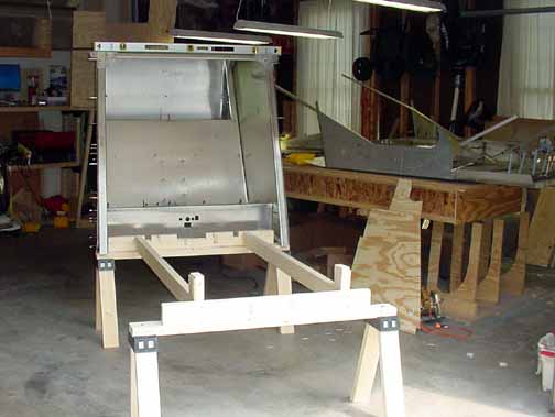
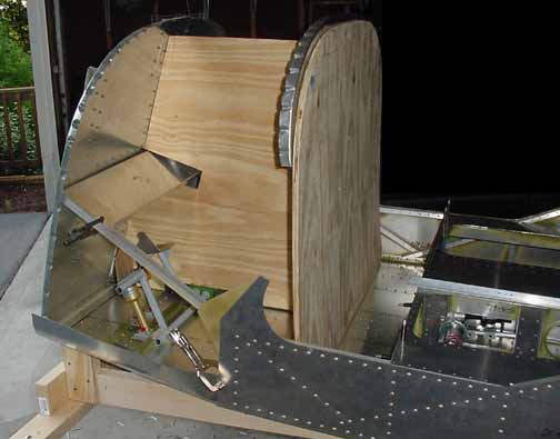
Here is the cradle, built according to the new drawings, in place to support the cabin. The forward fuselage is on the work table.
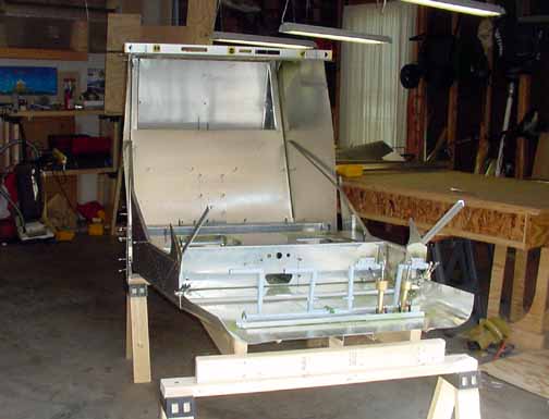
And here is the forward fuselage resting in its cradle. This is an exciting moment - it is really starting to look like an airplane - soon I'll be able to sit in it and make engine noises! I think I will add some lumber on the cradle where the rear and forward fuselage comes together for a little better support..
I have the tail all the way back to the wall. I think I could disassemble the work table at this point, and move it all into the single stall of the garage, but that would be cramped. I will put off doing that for a while. Lots of room on the worktable now.
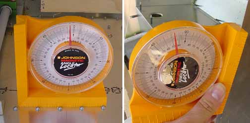
The cradle rested the cabin floor at 4 degrees as nominal, and the rear fuse opening was 74 degrees as nominal.
It looks like the sides are going to match up very well. Right now, it is pushed back as far as it will go without trimming the rear longerons about 20 mm..
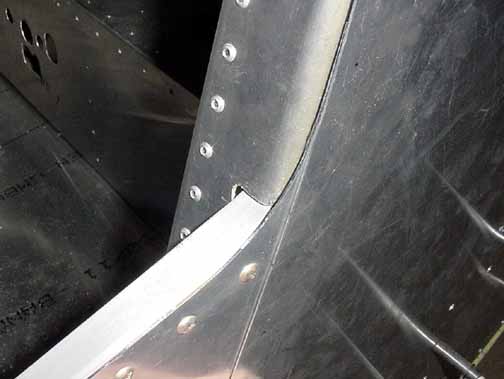
Here is how the front and rear come together - the rear frame has a cut in it to allow the longeron to pass through, and a thick doubler is riveted along side it to retain its structural strength. The holes on the side will be drilled as soon as the front and rear are aligned properly.
After the cabin floor and rear fuselage are joined (just cleco'd for now) I made the templates to position the firewall and instrument panel. Since the floor needed to be placed and removed several times in the process of joining them, waiting to put the heavy firewall and templates on makes sense. Also, the aft firewall stiffener is clamped in place.
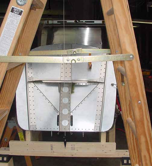
Before the holes for the rivets that join the front and the rear fuselage can be drilled, the front must be aligned to the rear. Here, a string was tied at the far rear fuselage on the centerline, then lined by sight across the front of the rear fuselage and tied to a ladder in front of the firewall. This provided a very straight line from the rear across the top to the front. Then, a string was suspended just above this line, with a plumb bob down near the centerline marks on the firewall. Then, the cradle was adjusted until everything lined up, and the initial holes on the sides were drilled and cleco'd.

![]()
![]()
Images on this website are either Copyright Zenith Aircraft Company and used by permission or are copyright Gary Liming