

Fuselage - 7th Page
June 8, 2002
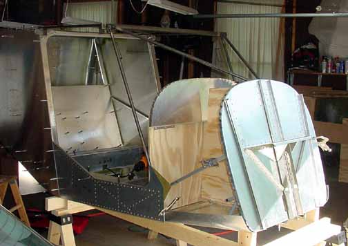
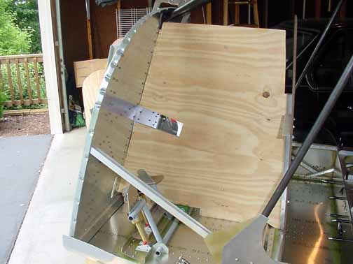
Here, the cabin frame has been put in place to cut to size. More than ever, it is really beginning to look like something to fly!
A 2x4 template is cut as per drawing (816mm wide) to set the distance from the front wing attach point to the rear wing attach point - this distance must match the wing spars width exactly. The exact distance in between the front and rear spars on my left wing is 825mm. Since the wing attachment brackets are 1/8 inch thick (3.175mm) the template should be 825 - 6.35 or 818.65mm, or about 2.5mm longer than the 816mm template on the drawing. I will just glue some 2.5 mm thick material to the end of the template. This may sound a bit picky, but there really isn't any give for the distances between the spars and the wing attachment points - they do need to fit to the nearest mm.
Jim Frisby told me he made an exact template by clamping aluminum to the wing spars, which helped set the distance. I did this, and here is how mine turned out:
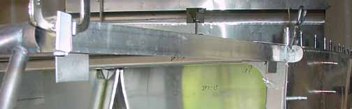
The aluminum is just hardware store variety, so don't use it on the aircraft. There are 1/8 inch thick "l"s riveted on each end that sets the distance. I am pretty sure the wing pickup points are right on the mark now.
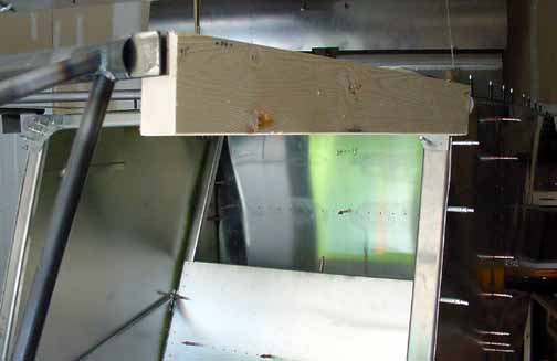
Something's not right. See the gap between the template and the firewall at the top? That shouldn't be there. The angle finder says the floor is at 4 degrees, and the firewall is at 71.5 degrees, and I verified that the template is cut at 75.5 degrees, so there should not be a gap here.
I verified the template dimensions, and I made sure the cradle was made to spec and was level on the floor. After much experimentation, including making a new template to hold the instrument panel because the old one was warping some, I found I could raise and lower the bottom of the firewall 25-30mm and the angle finder still read 4 degrees! I think this is the problem. I put a 3/8 inch piece of plywood under the rear saw horse, raising the middle a bit and the gap was much less. The measurements here need to be precise. Before drilling anything that sets this angle, I am going to get something more accurate.
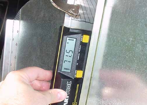
With this Smarttool angle finder (I got mine from Wicks), you can set angles to a tenth of a degree.
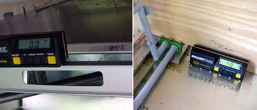
From the above, I adjusted everything until the readings were dead on, and then clamped and drilled. The left hand photo shows the top of the cabin frame resting level. The gap with the firewall template disappeared, and I feel much better.
While I waited for the angle locator, I made the left and right chairs. You need to pick up the exact distance between the rails mounted on the seat top (shown above at the very left for the right seat), but you can make the chairs anytime after that. The only tricky part is drilling the 1/16th inch holes in the 1/4 inch rods that protrude from the seat back frame into the hinge. This hole is for the cotter pin. I went slow and kept the drill straight and short, but I still broke 2 bits to get them drilled. I used the spring punch to make a slight dent in the rod, which did eliminate any wandering. Also, make sure the holes drilled in the rails match up your holes for the adjustment rod before drilling. This is all that is supplied for the chairs, so you have to upholster it from here. I think I will start looking into that.
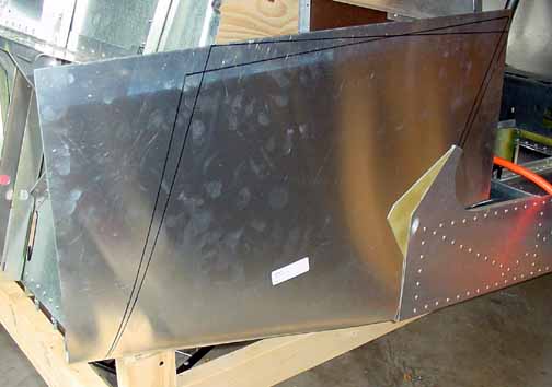
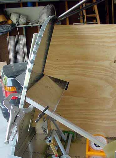
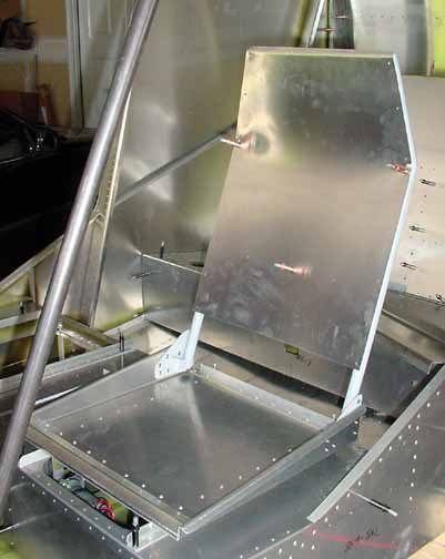
Now for the side skins. You need to make a curl on the front bottom using the same technique that was used on the wing root skin by wrapping the skin around a 3 inch tube, and a 90 degree angle on the aft edge. Then the bottom edge is drill and clecoed as above. On the advice of others, I did not cut the outline that comes from the factory, other than the notch that fits into the cabin side. In the finish placement, this front skin goes outside of the green piece that is exposed in the above photo. The two sets of lines mark the difference between what was marked originally, and what will be the final cut. There are "z's" that go inside the skin, and it is difficult to get to everything with the templates in the way.
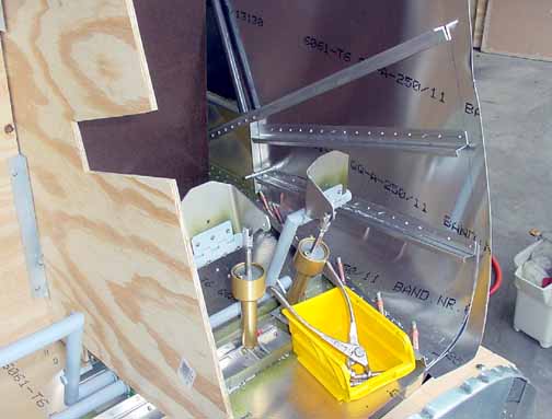
Here is the other side of the skin, with the firewall temporarily removed and the "z" stiffeners drilled in place. In order to clamp the "z's" in place, I rough trimmed the front edge.
![]()
![]()
Images on this website are either Copyright Zenith Aircraft Company and used by permission or are copyright Gary Liming