

Fuselage - 8th Page
July 3, 2002
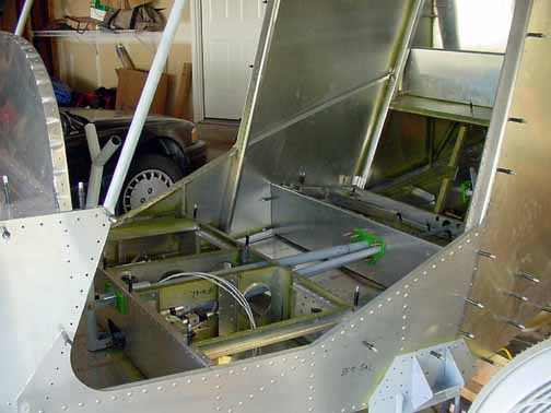
Above, the firewall has been painted, the cross support drilled, riveted, and bolted in place along with the engine mounts. The fire wall is only clecoed and bolted at this time. Also, both side skins are primed, drilled and clecoed, but the outside edges are still untrimmed.
If I had it to do over again, I would NOT have mounted the engine mount brackets (the gray triangular pieces above) until I have the engine mount that goes on the other side of the firewall and could see how well that lines up with the predrilled holes on the firewall itself. The manual calls your attention to not letting the drill wander while drilling, which leads you to believe there is an exact fit called for. However, the engine mount holes may not match the pre-drilled holes on the firewall by quite a bit, and that 4130 steel doesn't give much. So, get your engine mount, and use it as the drilling guide, not the predrilled holes.
So far, the only deviation from the plans I have made are the wing camera/light mounts, the aluminum fuel lines instead of rubber lines in the wings, and the removable fiberglass wingtips. I am going to deviate a couple of more places here - I need the instrument panel to be a bit more forgiving to the knees. Raising the panel would be a bit difficult - the top skin would need to be larger than what I have. Moving the instrument panel forward (away from the pilot) looks pretty doable, though. Since the top skin narrows as it lays forward, I might have to narrow the panel a bit. Since I only need to move it forward 20-30mm, there shouldn't be much to modify. I will re-cut the template and see how it fits.
Above, the instrument panel jig is back in place, the instrument panel is 30mm forward of where the plans locate it, and the gussets on the sides of the panel are drilled and cleco'd. There is still plenty of room behind the panel, and I didn't have to modify the panel at all.
Also, one other deviation from the plans - I located and cut the NACA air vents on both sides of the forward side skins. (NACA stands for National Advisory Committee on Aeronautics, a precursor to NASA, and they published a lot of research in the 30's-50's on airfoils and other airplane design issues. One of the reports concluded the above vent design presents the best vent pressure with the least amount of additional drag for subsonic flight. It is usually called a NACA vent.) The fiberglass piece behind the skin is one that Van's sells for just this purpose. On the inside, a 2 inch piece of SCAT duct is clamped on it and rather than take up panel space, I will make a mounting bracket for the eyeball vent right under the gusset on each side. The fiberglass vent will next be epoxied and riveted in place. It is easier to make this cutout now. Having good ventilation available (but able to turn it off!) is a safety issue as well as a comfort feature. Additional weight for the vents, including fiberglass, hose clamps, flange, eyeball vent, and hose is 8.2 oz per side, or 16.4 oz total.
Here, both sides are done, and you can see the reinforcement angles on the cabin frame, and the fiberglass vents from the other side. Its all ready for the top skin to be drilled and cleco'd.
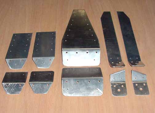
One more deviation is to add reinforcement to the seat belt attachments. I saw a picture once of a seat belt attachment that failed on an emergency landing - the AN bolt just pulled through the aluminum end, so I am going to double that area. The pieces in the top row are the .063 belt attachments that come with the kit, and the pieces below are the .063 6061-T6 pieces I have added to the ones immediately above. The two left pieces are the outboard front lap belt attachments, and the middle one is for both the inboard front lap belts. The two right pieces are the rear outboard lap belt attachments. The inboard rear lap attachment is steel, which is already roughly twice as strong as aluminum. Total weight addition of the lower row of reinforcements - 3.1 ounces.
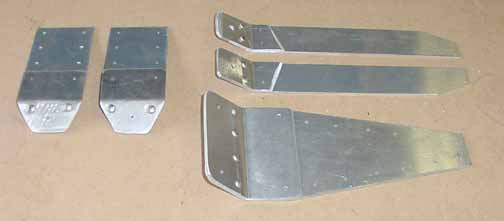
Above are the belt attachments reinforced with the thicker pieces and solid rivets. The other holes are pilot holes for the final installation.
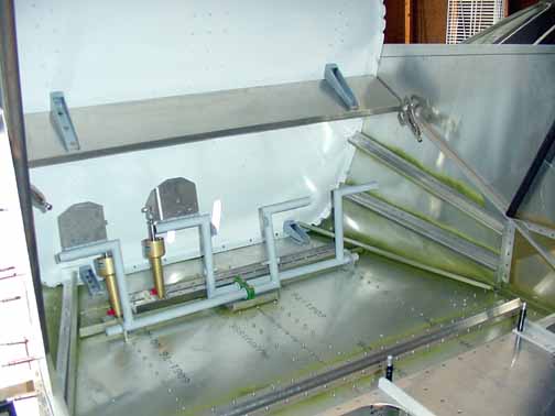
Above, I've removed the supports behind the rear seat to make it easy to install the elevator bellcrank and the rudder pulleys. There are two sets of numbers about where the bellcrank goes on these brackets, depending on when you pulled the drawing off the ZAC website. The later numbers weren't right for me. I had to raise the location of where this bellcrank went when I installed the rest of the controls because the push rod for the elevator would rub against the flap torque tube. I needed 3-4 mm clearance. I ended up with the center of the bellcrank at 80 mm instead of the 76 on the drawing. The pulleys are enclosed so that the cable cannot come off the pulley.
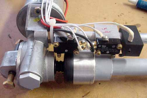
The wired flap actuator, viewed from the bottom. The wires go off to the flap switch on the panel and the power from the fuse. They are applied with ring terminals, heat shrink, and thread locker. To the far right is a runaway contact in case the up limit switch fails. It is an 8 gauge solid copper wire bent to make contact with the silver press fit ring if it goes past the up limit switch. Power from the switch is applied through a small hole drilled in the opposite end, and will melt the fuse if the limit switch fails. The wire is covered on both ends with heat shrink as well. Mark well the opposite ends of the wire, cut to the length needed to reach the final position of the flap switch, as each one is attached - it will save a lot of confusion later. At this point I attached the appropriate wires to the switch and a car battery to make sure everything was working.
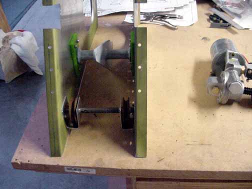
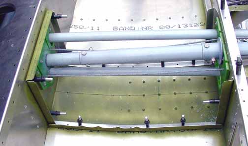
Here the actuator is installed with the controls in place. I found I had to widen the area in the green bearing material to allow the tubes to pass, but they have changed the dimensions on the drawings since. I would start with the dimensions on the drawings, and adjust from there until the controls move freely and aren't hung up on anything. Quite a bit of trial and error work here, but you need to make sure the controls are going to work smoothly without things rubbing against areas they shouldn't.
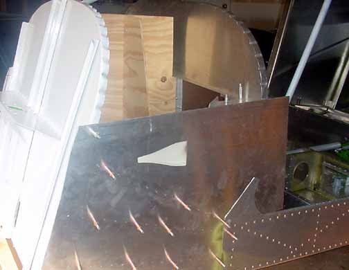
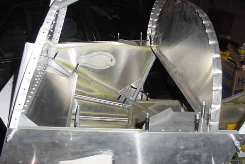
The center longeron on the fuselage bottom must be riveted while the main landing gear are removed. Also, the manual doesn't provide directions for it, but the rear seat tunnel for the controls shown on the drawings also must be riveted while the landing gear are off, so it is best to do them both at once. Above, the tunnel supports on the floor and the sides are cut and in place, using the fluting plier to match the curve of the floor.

![]()
![]()
Images on this website are either Copyright Zenith Aircraft Company and used by permission or are copyright Gary Liming