

Wings - 2nd Page
June 29, 2001
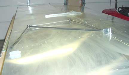
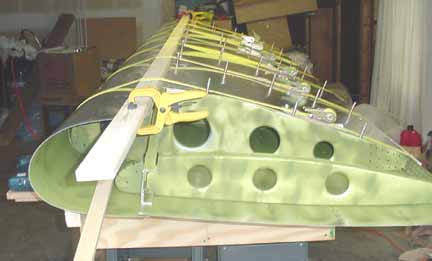
Below, the bottom skins are primed, drilled, deburred, and riveted. Another 8 hours to this point. Also, the main strut attachment bar is drilled, primed, deburred and riveted.
How does the diagonal of the jury strut go - with the diagonal attached to the front of the wing bottom, as shown below, or with the diagonal attached to the rear of the wing bottom, like it would be if flipped from right to left? I looked on the site, and the blue demo model, C-GECX has diagonal attached to the rear, while the red prototype C-GCUI has it attached to the front. (In earlier models it didn't have a diagonal, like in Stew Hicks' prototype.) Also, some of the completed models by some builders show it attached to the front. Alas, the only drawing I could find of the wings from the side was the "setting the dihedral" drawing, but it leaves the jury strut off! Another email to ZAC. (Email answered: the diagonal points to the rear, or opposite of what is shown below.)
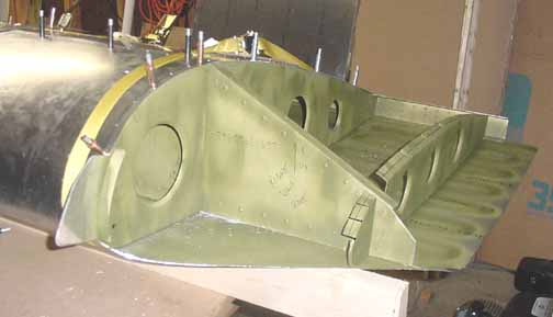
Below is taken at the same time, from the other end of the wing. I think both the jury strut and the tie down ring should be drilled now. (the drawing 8ZV-01 shows where for the tie down ring. You need to get the jury strut out to see how it will lay on your wing and place the brackets accordingly.)
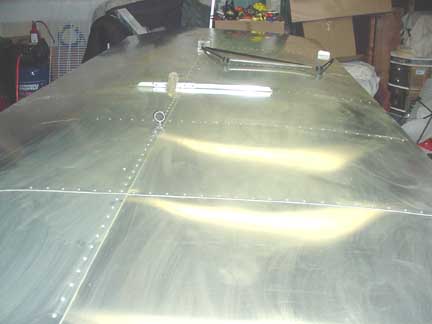
The haze you see is left over from wiping up some overspray of primer - I realized that leaving a thin coat of the primer on the surface would be good for it, so I spread it evenly over the wing.
Also, the next step is to flip the wing over and wrap the nose skins, and since the pitot tube is mounted in the nose, I think it should be fitted at this point if you are doing the left wing - I'm doing the right wing now.
July 14, 2001
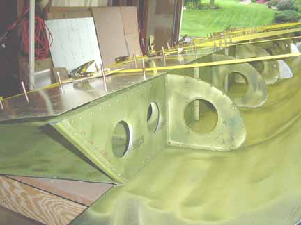
Above, the wing is flipped over, and the outboard end skins are trimmed, and a piece of std L is placed on the outboard end of the spar. The straps are in place for wrapping the nose.
There are pieces of cardboard under each strap mechanism to protect the skins, and wood is placed behind the trailing edge and long the front nose skin edge to keep the straps from deforming the edges. I am using 7 straps, one for each rib. A "rib adjustment tool" is shown above poking into the nose lightening hole, used to adjust the ribs as the nose skin is tightened. This shot from the root end.
Here, the edge of the nose skin is about to be tucked under the top skins for drilling. They will be riveted on the top of the top skins later.
Same root end, but with the nose skin trimmed back to size. This is where the challenging root skin piece with compound curves will be fitted.
July 21, 2001
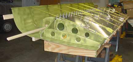
Now, the wing is flipped on its nose into some wings stands made from plywood. You can trace a nose rib onto the plywood uprights for a cutting pattern, but make sure there is 5 inches or so between the bottom edge of the board and the tip of the nose to make room for the slat brackets to hang freely.
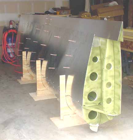
The trailing edge pieces are joined with clecos and placed over the rear spar, slipping under the skins. The tops skins are still only clecoed in place, as they must still be removed for the gas tank installation.
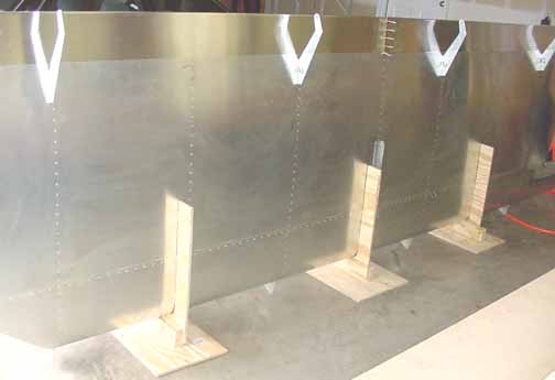
The flap brackets are already riveted in place, and the trailing edge skin rests on them while marking the rivet line into the rear spar on the bottom of the wing, shown above.
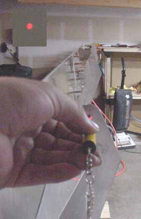
Here I've shined a laser through the holes in the flap brackets to see how well they line up - the upper left bright spot insert is the laser beam hitting the wall behind the flap brackets, after going through each one! The vacuum cleaner was there to suction the shavings from inside the wing.
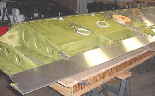
Above, the trailing edge piece has been riveted on the bottom, drilled along the top, and the upper skin has been moved aside. The tanks have been primed and are just resting in the bays to check for fit, and the supporting aluminum pieces to secure the tanks and the cork are sitting on top the wing, ready for installation.
The next step is to run the wires along the main spar from tip to tip. To do this, I am using some black, thin-walled ribbed conduit that is made for just this purpose. I got it for just a few bucks at Harbor Freight and it works great - the length you need for the wing is only 2.8 ounces, and it obivates the weight of grommets. I've seen the conduit at Radio Shack and some auto parts stores for a few bucks more.
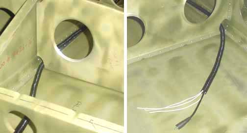
I have always thought that wing tip cameras were interesting, pointed either at the fuselage (this is the right wing, or passenger side) straight ahead, or even just straight down.. There are now very small color cameras that can be used that only needs 12 or 9 volts, for which I will run another power line. The camera only draws 100 milliamp. I am not sure how I will mount it yet, but I think I will run some thin shielded video cable, which will allow me to hook a camera to a video recorder in the cabin. The cable weighs 3 ounces for the 14 ft wing length, not counting the ends with a jack.
Above is a picture of the wiring conduit, passed along the existing hole where the ribs meet the bottom of the spar. There are four wires going to the wing tip - +14v for the cam, strobe and nav lights, and a common ground..
Next, is installing the tank brackets and cork.
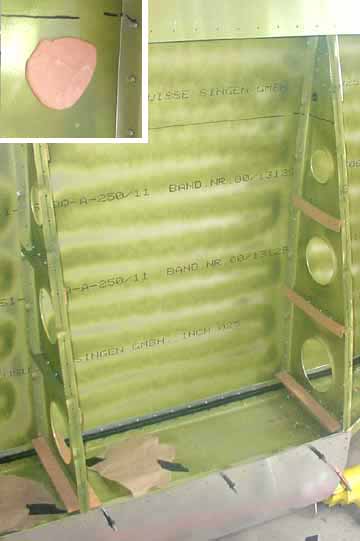
Above, the wing is back in the stand, and the brackets along the ribs have been riveted, and cork applied to them and to the tank, so that the tank is ready to fit. One problem that arises is getting the exact location of the drain hole that must be drilled into the bottom skin. In the upper left insert is a picture of some Silly Putty that I pressed into place on the bottom skin where the drain hole should be.
(I got this idea from Dave Zilz - he specified MIL spec AN-2385-O-39 Playdoh, as recommended by his daughters, but I substituted ISO 37893-7 Silly Putty. I hope the substitution will work out ok! ((Just kidding, Dave ;^) ))
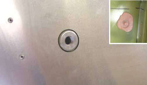
Then, I carefully put the tank in place and pressed the fitting against the putty. From the impression, as shown in the upper right insert, I was able to place a center punch in the center, and drilled it out to 1 inch with a Unibit step drill. That's a pretty good fit! Before doing this, you must make sure you have all the needed cork in place and everything on the tank is ready to go before setting it on the putty. This hole is smaller than the one specified in the manual, but after an email to ZAC, Nick said it could be smaller as long as the welding crown around the fitting doesn't interfere with the edge of the hole.
Back to 1st Wings Page Continue to 3rd Wings Page
![]()
![]()
Images on this website are either Copyright Zenith Aircraft Company and used by permission or are copyright Gary Liming