

Wings - 3rd Page
August 12, 2001
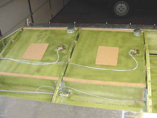
Here, the tanks are installed, wired and plumbed. Wires from the fuel gauge senders are run through plastic tubing as they pass through the ribs, and are held in place by a daub of RTV silicone. Ground wires are run from the tabs on the tanks to a bolt secured on the rib.
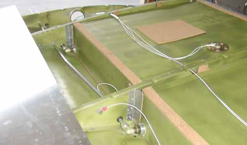
Another shot of the plumbing. Swagelok fittings are used to route the aluminum tubing.
Wires coming from both the wing tip and the fuel tanks are labeled and await a connector. Next, we cut the holes in the top skin for the fuel filler necks and the sender access panels, and cleco the top skin in place.
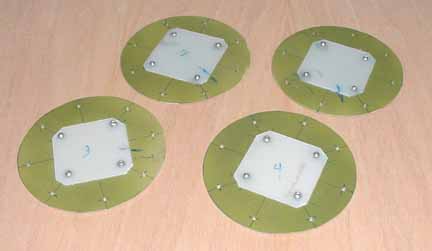
Made 4 covers for the fuel senders with nylon plate protectors so that access can be made if necessary in the future, 2 for each wing. 3 hours.
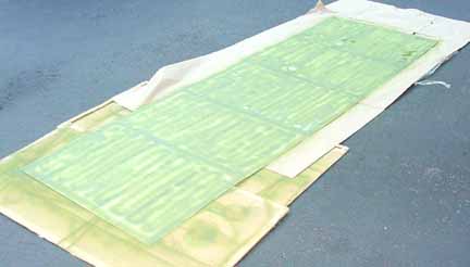
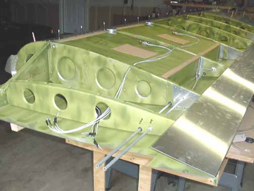
The upper skin is primed and ready to fit.
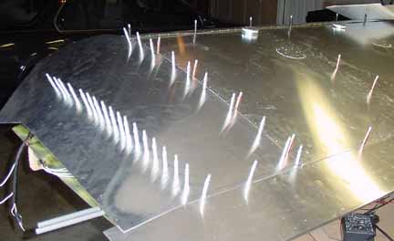
Above you can see the upper skin in place with the fuel gauge sender covers riveted in place, and the root skin beginning to be clecoed in place.
The rear and the pre-drilled holes have been clecoed, now all that remains is the compound wrap. Despite the instructions, this skin does not get riveted until the final assembly when the wings are attached to the fuselage, so I will tuck the sheet metal under the front and wait until that time to rivet the root end.
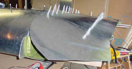
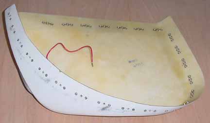
Above, the wing tip has been trimmed, the angle flange applied to the upper tip edge, and the fiberglass nose tip is being fitted and drilled. The strobe bulb socket has also been attached to the side of the fiberglass. A critical part of the STOL feature, this Hoerner design also looks very cool. How do you cut the right lines? As Michelangelo said about sculpture, you just cut away everything that looks like it doesn't belong. Take your time, though, and sneak up on the right shape. One bad cut here and you've got a real problem.
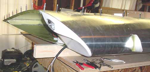
The fiberglass piece will be made removable so that the supply as well as the bulbs may be serviced. I am making it removable by using nutplates riveted on the back of the fiberglass, and 6-32 stainless screws on the front. How much weight does it add? There are 25 holes around the tip. Each nutplate weighs .700g, each screw weighs 1.00g, each used A4 rivet (without the mandrel) weighs .256g, and each 3/32 rivet is .071g (if you happen to have a lab grade scale, why not use it?) So, the attachment device weight using rivets would be (25x.256) 6.4g, and the screw/nutplate with small rivets would weigh (25x0.7)+(25x1.0)+(50x.071) = 46.0g, or a difference of 39.g. (this is just 1.4 oz.) I can live with that. I think you could get away with fewer screws, but I stayed on a 40mm pitch. 2 hrs to put on the nutplates.
The strobe power supply is mounted on the spar right by the fiberglass, as below:
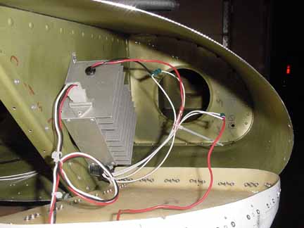
All of the above wires will be tucked into a piece of the black sleeve and supported.

Above, I've made a bracket to support the jacks for the video camera. Nutplates will be attached around the hole, giving the bottom plate something to screw into. If I don't want the drag of the camera, I can just put a blank plate on. If I want the camera, I just connect the jacks, screw the plate on, and the video signal will feed into the cockpit. For more info on the camera, go to the instruments page.
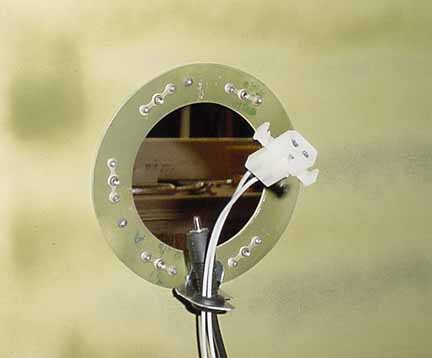
Above is the mounting ring from inside the wing. It is a ring of scrap with 6 nutplates riveted to it with small flush rivets. The ring is then riveted to the wing skin with four flush rivets. This allows the cover plate or camera plate to be screwed in place flush with the skin. I cut back the wire support bracket - the original one was overkill. More black sleeve goes over the wires.
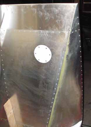
Above, the wing is upright in the stand and the wingtip skins are riveted in place, and the white camera hole blank plate is screwed into the nutplates.
Back to 2nd Wings Page On to 4th Wings page
![]()
![]()
Images on this website are either Copyright Zenith Aircraft Company and used by permission or are copyright Gary Liming