|

|
|
The Gap system is an electromechanical set up to position the electrode over a piece of clamped-in-place work material, and then maintain the resulting gap between them as the material erodes away. It is also very convenient to be able to position the electrode accurately over the workpiece, so an X-Y table is usually employed. To start with, we need a frame, a linear actuator, and some clamps. This assembly that lowers the electrode is sometimes called the ram, even though the electrode should never actually touch the work material. We'll start with the ram. The ram's actuator has little need for mechanical position feedback since the gap will be maintained by feedback from the electrical discharge. Therefore, a stepper motor or servo motor with encoder is not needed.
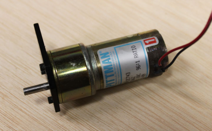
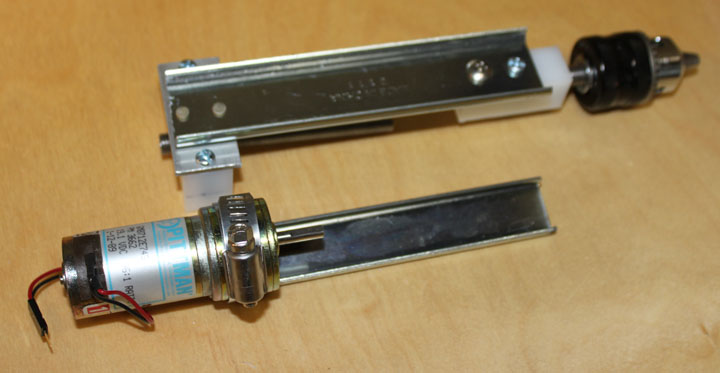
Fig 1 The ram then will be driven by an inexpensive ($13!) gear motor with an 80 rpm output shown in Figure 1 that will turn a threaded rod. This assembly will be mounted on sliding rail.
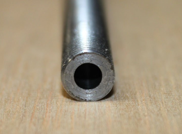
Fig 2 The 3/8-24 threaded rod needs a concentric hole to receive the .187 motor shaft. For that, Frank Kerner, a good friend who has lots of experience as well as a very nice lathe and a good set of drills and reamers helped me get a perfect fit.
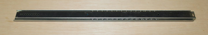
Fig 3 Since there are no sideways forces during operation, or even much in the way of vertical forces (besides lifting its own weight), no elaborate rails or bearings are needed as long as there is very little play in them, so a simple drawer slide will be used per Ben's plans. The travel of the slide only needs to be long enough to get the electrode out of the way enough to mount and dismount the work, say 1-3 inches. The one I used was an under drawer mount that I bought at a big box store - model Knape & Vogt #1129, just under $5.
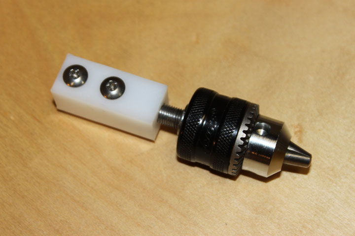
Fig. 4 Above shows a replacement Jacobs chuck screwed onto a segment of the 3/8 threaded rod shown in Figure 2. It is also screwed into a piece of 3/4 x 3/4 UHMW plastic that also has two #10-32 holes tapped into it. These stainless #10 screws will secure the chuck to the slide. The plastic insulates the chuck and electrode from the rest of the machine. I think I will add a jam nut against the chuck as well as a soldering lug.
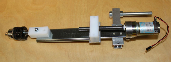
Fig. 5 Here I've deviated from the book slightly - I wanted to keep the drive screw and chuck of the ram centered down the slide, so I mounted the chuck centered, and made an aluminum mounting plate for the lead screw nut. The plate was flush riveted to the slide. The screw nut is made of UHMW, (ultra high molecular weight plastic) ideal for an anti-backlash nut and threaded for the 3/8 rod in the middle, with bolt holes on either side matching the mounting plate. The hole for the drive screw was placed after aligning everything with the motor in place. I've also deviated from the plans by making the slide assembly about an inch longer, just to provide more clearance as well as allow the electrode to be placed deeper into some objects. The other side of the slide and the screw are lengthen to match. The motor is mounted to the fixed part with a simple hose clamp. All in all, it fits together very well. I still need to glue the drive screw to the motor shaft with a wavy washer, and bolt a piece of square tubing on the fixed part of the slide to provide a handle for the ram.
Fig. 6 Here is the finished ram assembly, ready to zap! I epoxied the threaded rod onto the motor shaft with a wavy washer and a nylon washer to take up any play in the motor bearings. I added another flush-riveted mounting plate for the square tube cross arm, and part of a 3/8 inch bolt into the square tube arm. Mostly, these mounting plates were done because it was too hard getting a pair of nuts or a bolt heads inside the slide - this way, only flush rivets end up inside the slide aligned down the middle. I've taken steps to make sure that everything is aligned for a smooth vertical travel. If you apply +12V to the motor, the electrode chuck descends, and if you apply -12V, it ascends. With the longer length, I got eight ball bearings in the slide - there is now very little play in the slide. The rear bolt will go into my drill press chuck and allow me to use my drill press as a stand with an adjustable table for now, although I may later make its own stand over the tank. One other improvement I may make is to modify and bolt one of those inexpensive digital calipers to the slide, giving me a DRO type indicator that will allow me to control the depth of cut with some precision. And, it might be fun to watch the numbers increase as the cut proceeds.
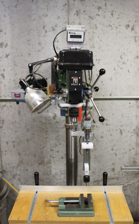
Fig. 7 Above is the ram chucked in my drillpress. Where the vise is, the tank will be placed. I will try to remember not to turn the drill press on when it is in this configuration! |