|

|
|
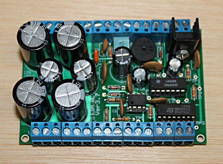
Fig. 1 The first step in creating the power system is ordering all the parts and populating Ben Fleming's version 3.7 PC board. The completed board is shown above.
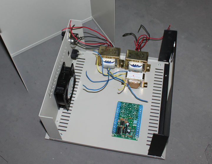
Fig. 2 The next step was in getting a project box to hold all the parts and start thinking about the layout of things. Project boxes are pretty expensive anymore, but luckily I found a used one at a local electronics surplus store that I could adapt fairly well. This 11 x 12 x 5.75 inch box will house the resistors that will generate heat, as well as the main cutting capacitors that need to be cooled, so a fan is needed. I'll block off some of the vent holes to direct airflow. The main supply calls for about 50 volts at several amps, and there wasn't much in that way of transformers around, so two 24 volt transformers wired in parallel with give me 48 volts. There is also a third 12 volt transformer that needs to be mounted, as well as the partially populated PC board of Figure 1, a fuse holder, bridge rectifier, power connector, and jacks for the cable connections to the actuator motor and to the electrode. Above, I've just laid things in the box to get a feel for a good arrangement that will facilitate good wiring practice and parts cooling.
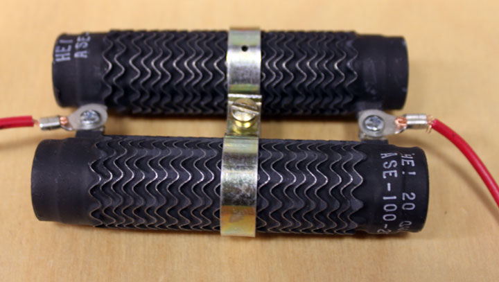
Fig. 3 I found the above 20 ohm 100 watt power resistors on Ebay for $4.50 each and they are 3.5 inches long. The spec callls for a 10 ohm 100 watt resistor, so these two in parallel will provide 10 ohms at 200 watts. They came with the mounting straps.
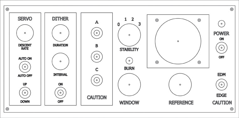
Fig. 4 The front panel controls for the device consists of a meter, 5 potentiometers, two LEDs, and 9 switches (one is a rotary). This necessitated some kind of layout for the front controls. I came up with the one shown above. From this CAD drawing, a toolpath with be generated to CNC cut the holes, and the labels will be printed on a laser printer.
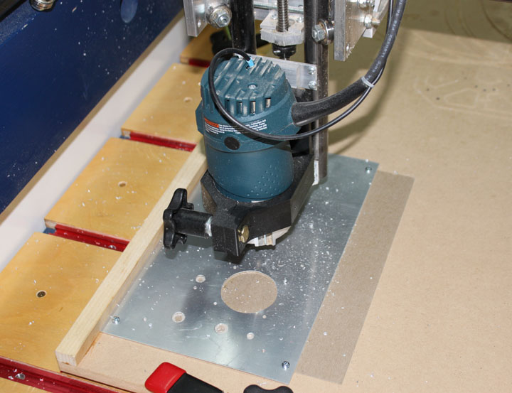
Fig. 5 Above shows the .032 aluminum panel being cut on my homebuilt CNC. The panel above is oversized so that I could screw it to the sacrifice board. After being trimmed, it will be cleaned and painted.
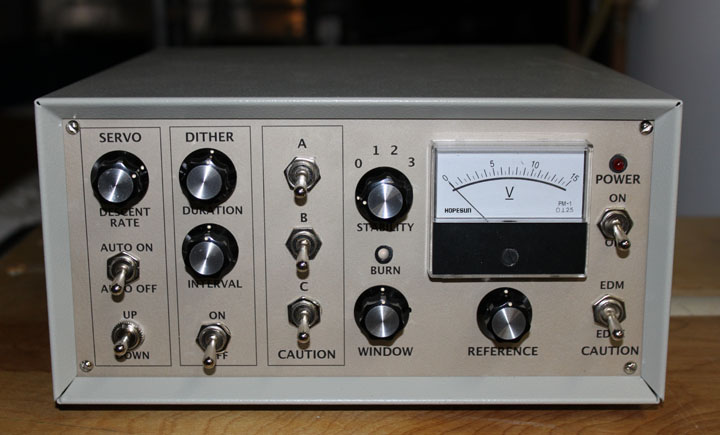
Fig. 6 Above shows the painted and labeled panel with the switches, knobs, LEDs and meter mounted. I've grouped the controls for the servo descent into a box on the left. The "Up Down" switch just allows you raise and lower the electrode, or ram. The Auto On/Off turns on or off the automatically lowering of the ram as a function of the current used by the burn. The upper knob allows you to control how fast the motor descends. The next box controls dithering. Dithering is engaged by the On/Off switch and simply backs out the electrode every so often, how often controlled by the Interval knob, and waits a bit for the gap to be flushed out - how long it waits is controlled by the Duration knob. The third box are three switches that add capacitance into the high voltage circuit to increase or decrease the discharge current which affects the fine or coarse finish, as well as cutting time. The Window and Stability controls set up the gap at the best current flow. The Reference knob sets the point at which the ram starts to be lowered. I may try a custom face for the 0-15V meter, which actually measures 0-150 Volts. The "Burn" LED is a red/green bipolar LED that is red when the servo is descending and green when the servo is ascending. There is a red LED above the power switch that lights up from the +12V supply (it's not in the plans - I just don't want to leave this thing on accidentally), and the switch under the power switch flips the unit between EDM mode and "Edge Finder" mode, which simply sounds a buzzer when continuity is detected between the electrode and the work piece. The "Caution" label under some of the switches is just a reminder not to throw those switches while cutting, or the power will arc across the switch, potentially ruining the switch.
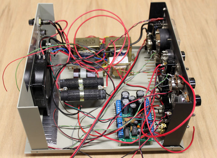
Fig. 7 In the middle of wiring.... Just about all the components have the right wires on them, and now they just need to be connected to the PC board. The power resistors are placed right in front of the fan, and the main capacitor is next to them. The airflow is right to left and out the fan. The PC board is mounted on some nylon standoffs. Project Currently on Hold - Stay Tuned |
|