 MOUNT MOUNT
|
|
|
Fig. 1
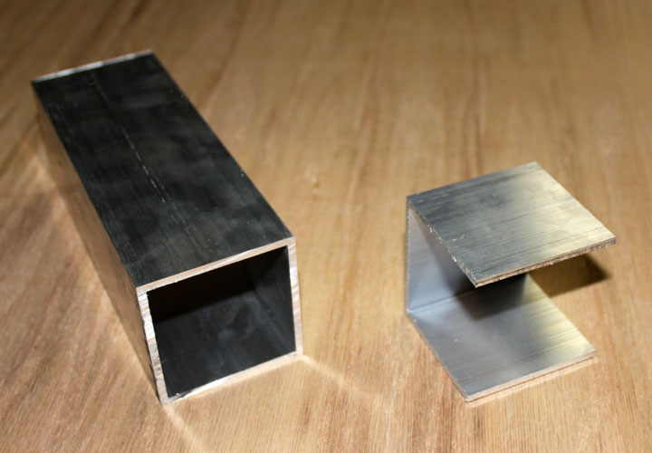
The mount for the binocular needs two degrees of freedom, or two pivots. There are two secrets of getting all the joints on the mount to work smoothly but yet stay put when let go. One is keeping each joint balanced, which can be done either by adding counter balance weights (like on the parallelogram) or by locating the pivot at the center of gravity for that axis. The other secret is keeping the pivot bearing surfaces as large as possible with a slick substance, like Teflon. Getting those pivots in the small space between the end of the parallelogram and the bino attach point can be done in wood, but given the weight involved they start to get pretty clunky looking. Therefore I decided to deviate from the Simmons design and my own desire for wood and use a bit of metal, especially considering I already had some of it. I cut a 2.5 inch length of 2.5 inch square tubing, and cut off one of the walls, forming the bracket on the right in Figure 1. The material is 6061-T6 aluminum that is .125 inch thick. This bracket will form the base for both pivots. The corners now need to be rounded off.
Fig. 2
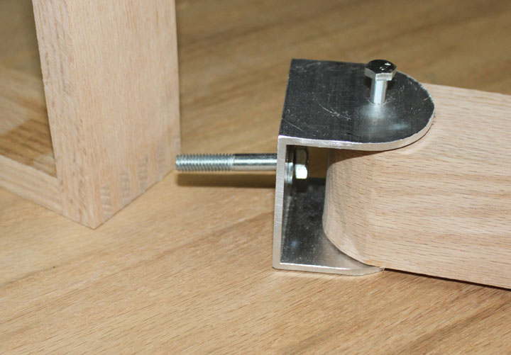
The above picture shows the bracket with corners rounded and the flats drilled to accommodate a 1/4 bolt vertically and a 5/16 bolt horizontally. The oak block on the right has also been rounded to provide a swivel of about 180 degrees, and it's height is that of the inside of the aluminum "U" with a bit of space for the Teflon washers. The "L" bracket on the left was made using a finger joint which has proven to be quite strong, as the joint usually fails outside of the glued surfaces, but I will probably add a couple of "L" braces on the sides anyway. The hole for the horizontal bolt in the "L" bracket will be placed depending on where the center of mass is for the larger binoculars.
Fig. 3
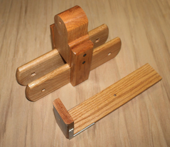
Above shows the rounded pivot block that was shown on the right in Figure 2 mounted onto the parallelogram verticals. It also shows the "L" bracket finished with some steel elbow reenforcements.
Fig. 4
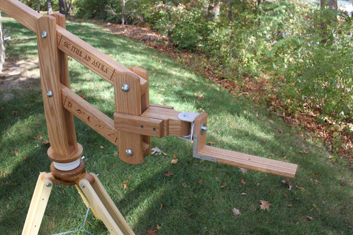
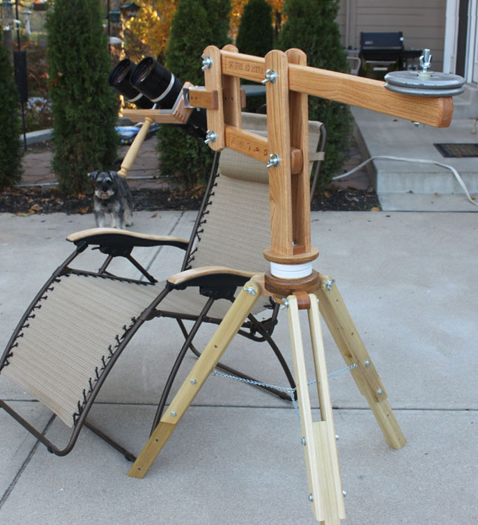
Above shows the finished mount ready for the binos. Keeping the the right tension on the pivot bolts is what keeps everything in place. I think I may add a handle under the bino platform to make moving the binos around easy. The length and double thickness of the top beam of the parallelogram serves to offset the weight of the mount on the right, so whatever the binos weight (10 lbs) is the weight needed on the other end to keep it balanced.
Fig. 5
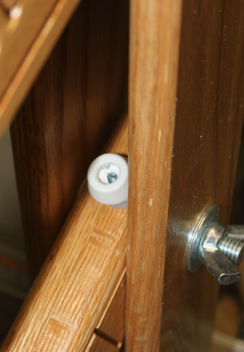
On a discussion thread on Cloudy Nights, someone pointed out the dangers of getting pinched in the parallelogram. I believe rounding over the edges of the wood helps prevent the skin pinch that results in blood blisters, but one of the forum members said they had someone break a finger in one! Here's a simple fix - those rubber feet/bumpers with a spacer high enough to equal the thickness of a finger will prevent that from happening by making sure the parallelogram cannot close all the way.
Fig. 6
Above notice the handle, which was part of a chair leg that I glued a length of 1/4-20 allthread in the top, that serves to attach the binos to the mount. It also serves to position and hold the binos while viewing. At this point, it is ready for stargazing! The Bino Chair |