 PARALLELOGRAM PARALLELOGRAM
|
|
|
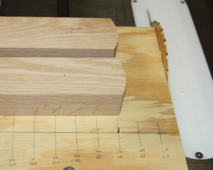
Fig. 1 I started with the main arms of the parallelogram. These need to carry not only the weight of the binoculars, but the weight of the counterbalance as well. Therefore I glued two pieces of 1x3 oak for each arm, making the resulting piece 2.5 x 1.5 inches. The arm that will hold the counterbalance weights I made longer at 30 inches to start, and lower arm 18 inches long Although not necessary, I like to have the ends rounded off if possible, so I mounted them on my jig to cut round things on a table saw. I have the index pin (the nail in the bottom plywood jig) at a 3 inch radius. After tapping the arms onto the pin, the jig slides in the miter track along the sawblade while I turn the arms around the index pin, giving the rounded ends shown above. Next, I'll hit the edges with a roundover bit.
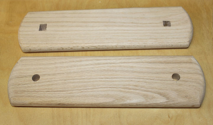
Fig. 2 Above are the shorter verticals that have rounded ends and a roundover bit along both sides. The top one has had the holes squared for the head of a carriage bolt. I think the roundover will significantly reduce the likelihood of pinched fingers that is associated with parallelogram mounts.
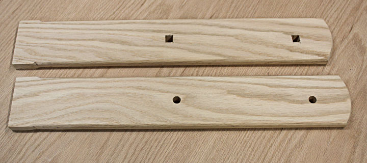
Fig. 3 These are the longer verticals, also with square holes for the carriage bolt heads. The square ends on the left form tenons into the base.
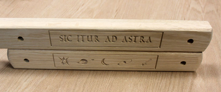
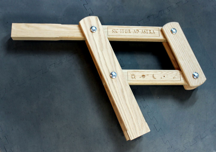
Fig. 4 Here are the upper and lower arms rounded and drilled. I decided to spruce them up a bit with some CNC carving. On the bottom I used some astronomical symbols, and on the top I chose a Latin phrase from Virgil's Aeneid, "sic itur ad astra" which means "and thus you shall go to the stars."
Fig. 5 Above you can see the basic parallelogram assembled. The bottom of the longer uprights go into the base of the tripod, and the shorter uprights will get an arm to attach the bino mount. The upper left arm will get a shaft to accommodate the main counterbalance weights.
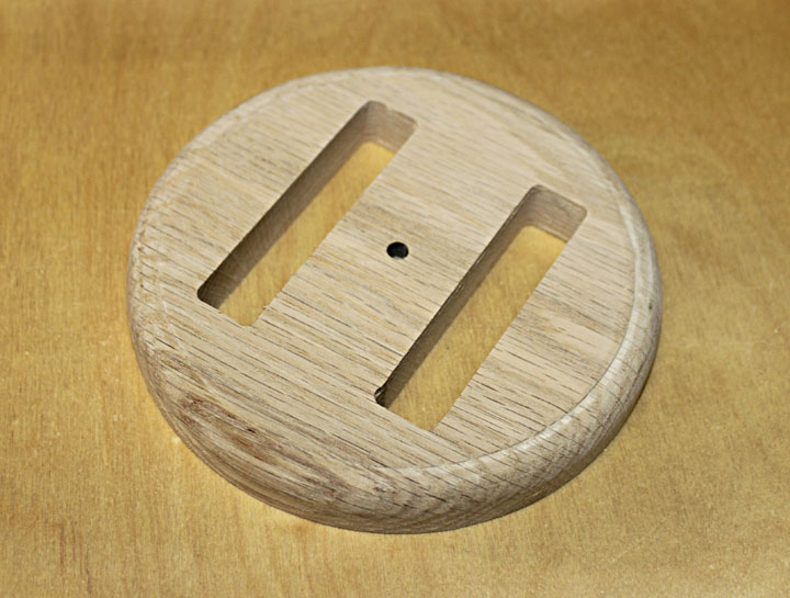
Fig. 6 The base the parallelogram uprights fit into. This also gets a bearing surface, and drilled through for the main pivot bolt.
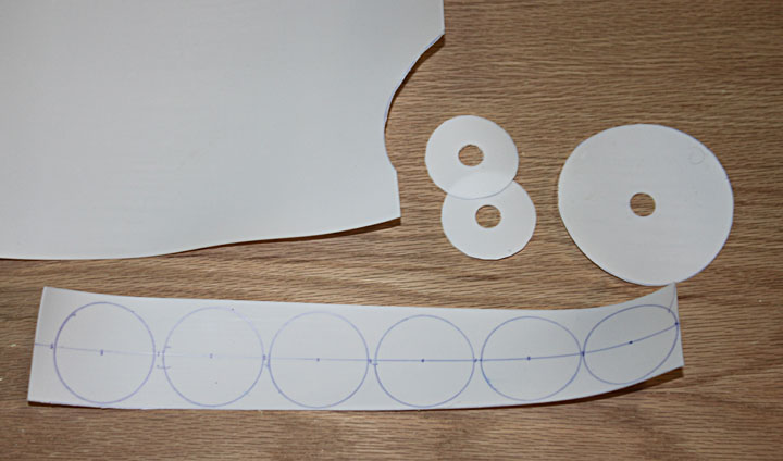
Fig. 7 The movement of the parallelogram seems to "stick" a bit when left in one position for too long, so I am using a 1/16 inch thick PTFE sheet to make some teflon washers. The large one is for the azimuth bearing on the tripod as well.
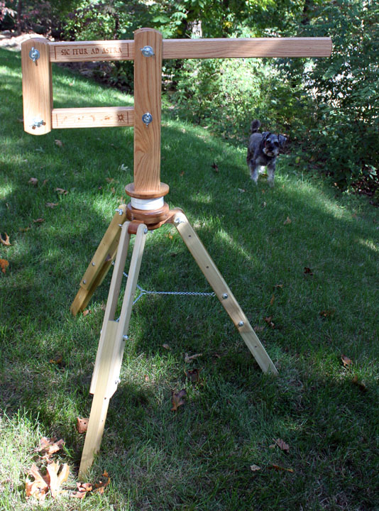
Fig. 8 Here is the parallelogram placed on the tripod. The arm on the right will be drilled to accommodate a bolt to attach weights to counterbalance the binocular and its mount. The azimuth movement is smooth, as well as the up and down movement of the parallelogram. That's two degrees of freedom down.
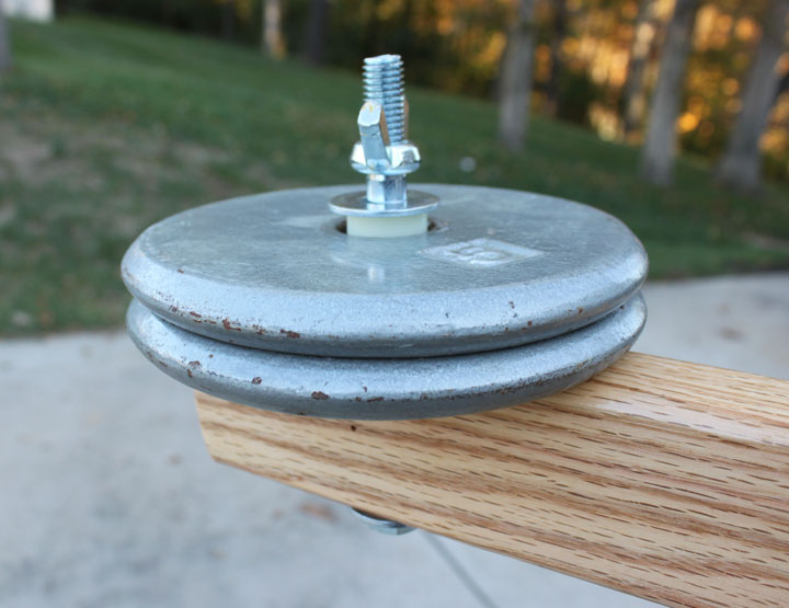
Fig. 9 This shows the attach point for the counter weights. It is simply a 1/2 inch bolt with some 1/2 ID to 1 inch OD nylon spacers and a wingnut. The weights are easily removable so that the whole thing is packed in five sections - the chair, the binos, the tripod, the weights, and the parallelogram, each one of which are only about 10 pounds. Next is to make a mount for the binoculars that allow for a few more angles of movement. The Bino Chair |