 TRIPOD TRIPOD
|
|
|
Fig. 1
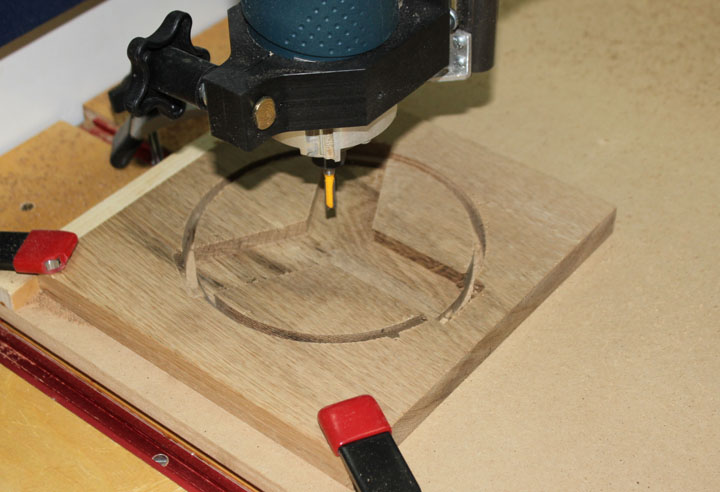
The tripod starts with the head mount, where the legs come together. Above shows a 6 inch diameter piece of 3/4 inch oak being routed to form 1 1/2 by 3/8 deep slots for the leg attachment arms. You could do the same by hand with a plunge router if you are careful. Another 6 inch round piece glued to this one will provide a strong and wide mounting head.
Fig. 2
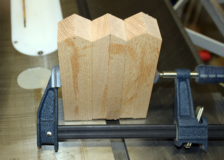
The above picture shows the leg mounts that will go into the head. I cut 6 1x2 by 6 inch oak pieces and then cut a 30 degree angle on one end. Above, they are glued and clamped as 3 identical pieces. They will be cut to length as needed after I see how they fit in the head. I am planning to use 3/8 inch carriage bolts for the pivots.
Fig. 3
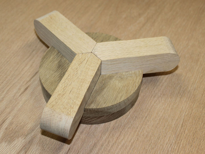
Above shows the head assembly upside down. I think I will make another piece like in figure 1 only 4 inches diameter to complete the bottom of the head. Each leg mount will be drilled with a 3/8 inch hole in the rounded ends, and a 1/2 inch center hole for the head mount will be drilled.
Fig. 4
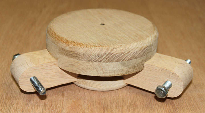
The head is just about done, but the bearing must still be glued and screwed to the top.
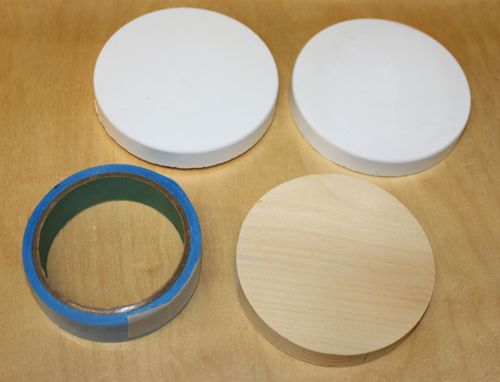
Fig. 5
Above are the bearings that will provide movement around the center axis (azimuth) of the tripod, so the weight of the whole upper assembly, including all counterbalance weights and the binoculars, will be on this turning surface. It consists of two PVC drain end caps for a 4 inch pipe sanded flat and cut to 1/2 inch deep. (A regular end cap for a PVC pipe is usually spheroid, not flat.) Each one will have a 3/4 inch wooden base inside it, like the one shown lower right. One goes on the top of the tripod, and the other goes on the bottom of the parallelogram. Where the two PVC surfaces meet, I was going to add a layer of Teflon adhesive tape, shown on left. I later discovered that I needed a thicker piece, as shown on the parallelogram page.
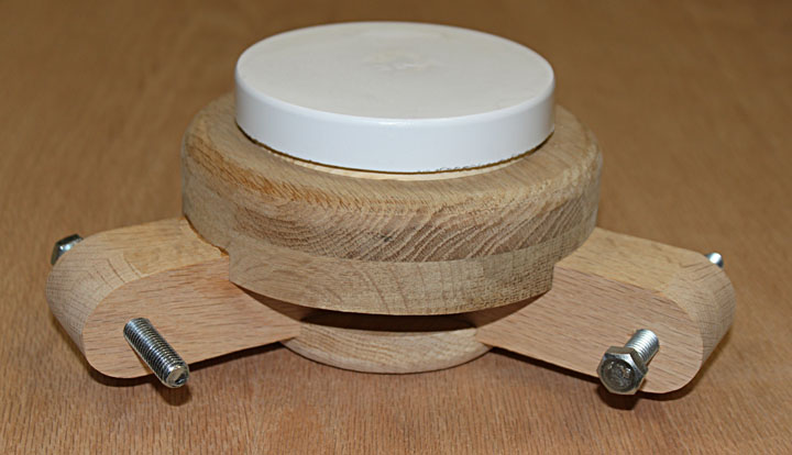
Fig. 6
The bearing is mounted on the head, which is complete except for the axial hole and a coat of finish.
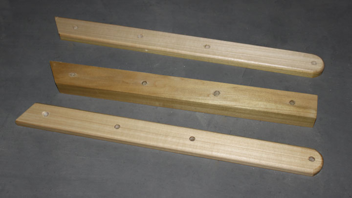
Fig. 7
The legs are made of poplar to cut down on weight. The middle section can be positioned up or down the legs to provide for three height settings.
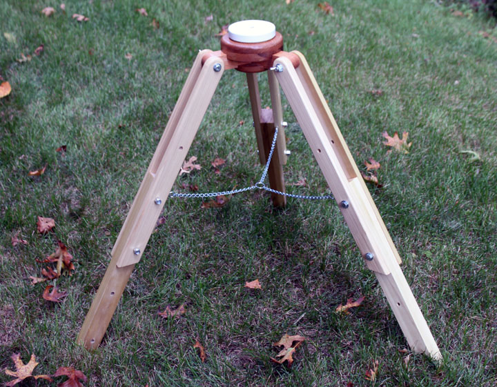
Fig. 8
Voila! The legs are bolted onto the head, a coat of finish applied, and three segments of chain on a key ring provide leg bracing. This should prove to be a stout base for several different instruments. I do some woodworking, so I had all the oak on hand, as well as some of the poplar leaving just the hardware - bolts, PVC drain cap, chain, and Teflon sheet to buy.
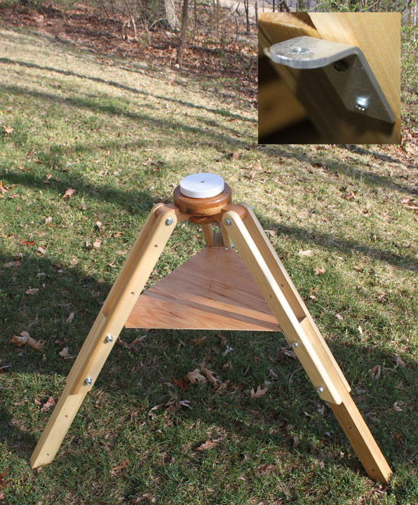
Fig. 9
After using the setup over several sessions on both turf and concrete pavement, all seemed well. Then I was asked to show the bino chair at a DIY astronomy club meeting, which had me setting it up on a waxed tiled floor. I was a bit embarassed - as I turned the parallelogram, the legs kept sliding and made the top of the tripod get out of level which hadn't happened before. I figured I needed to replace the chain with something to keep the legs more rigid, so I replaced it with a simple spreader shelf. First, I made three brackets from 1/8 inch strap aluminum, bent at 120 degrees and drilled, shown in the upper right of Figure 9. Then I cut a piece of 1/4 inch plywood to fit and drilled it to match the brackets, holding it place with some 1/4 inch bolts and wingnuts. This means one more step to do during set-up, and one more piece to carry, but the tripod is quite rigid now, regardless of what surface it is on. Plus, there is now a shelf to place things next to the chair, like a nice adult beverage. The Bino Chair |