

Fuselage
Jump to 2nd page Jump to 3rd page Jump to 4th page
Jump to 5th page Jump to 6th page Jump to 7th page
Jump to 8th page Jump to 9th Page Jump to 10th page
December 19, 2001
I picked up the fuselage kit today, unloaded it and stored it away. There is now the manual, the errata sheets, the drawings to go by, and the advice from other builders, and they all need to be studied! Contrary to the manual, I was advised by ZAC to do the sides first, according to the new measured drawings, and then do the bottom and top skins. I am going to describe how I did mine, but you need to make sure you follow all of the proper information given. Before taking any advice here, remember there are many different ways to do it, and please read the disclaimer. I do thank fellow 801 builders Dave Zilz, Phil Owens, Ben Haas, Rich Bauer, and Jim Frisby for their advice.
First of all, there are important symmetry issues here - you must make mirror images of the two sides for them to fit together properly. Also, I found it helps to mark the skins and their attachments "right" and "left" and "This side Out" and "This side In" to help keep things straight at this stage.
The side skin comes in two parts - with both laid in their proper place on the table, the side sticks out about 6 inches from both ends, and that is without the forward fuselage. If I clear out the rear area up to the wall of the garage, I think the rear and forward fuse sections will fit together, but the completed fuselage will definitely not fit in the garage with the engine attached.
The manual says to go ahead and cut out the skins along the outside of the outline that is drawn on it from the factory. Thanks to some advice from other builders, I will wait to cut out the skin until after the longerons are in place.
January 5, 2002
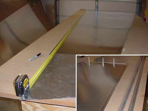
The first thing I did is mark where the two pieces of side skin overlap so that they have the correct length as called out on the drawing. Then drill and cleco the two skin pieces so that they are aligned and together from the correct length. The photo above shows the skins "inside up." Then, I marked the upper and lower longerons (both sides) with the usual 10 mm center line so that the predrilled holes along the top and bottom will fall correctly on the longeron. The marked longerons are shown in the lower right insert.
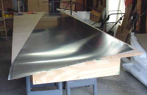
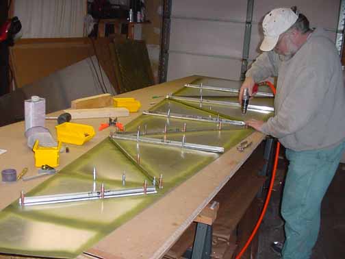
I then turned the skin over and clamped the ends of the longerons onto the skins obeying the reference points on the drawing and lined up the centerline of the longeron with the predrilled rivet line on the skins. Then, I placed 2x4 lumber under the longerons and began drilling and cleco'ing, like shown above. The picture above hides the longerons, but they are under there.
Once the longerons are drilled and cleco'd, I ran a marker (the thicker "fine" point Sharpie) down the outside of each longeron, making a mark on the skin that perfectly outlines where the longeron edge falls. Next I marked centerlines in all the standard "L"s, and began lining them up for drilling. I removed the longerons and placed some support lumber under each rivet line for the vertical and diagonal std "L"s, and drilled and cleco'd them into place while just letting the ends stick out for now. Remember to keep the bent side of the "L"'s toward the front for the verticals, and although an email from ZAC said it didn't matter for the diagonals, I kept the bent side of the diagonals on top as per the drawing.
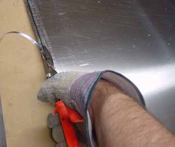
Next, I removed the longerons and flipped the skin over (now "inside up" again) and cut away the excess trim, just leaving about 1mm of the marker line. After the skins are trimmed, and it is a lot of cutting, I put the longerons back on and used a drum sander in the air drill that did a good job of getting the last 1mm or so trimmed evenly with the longeron. They are the 2 inch sanding drums from Sears.
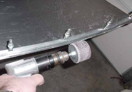
Although freehanded power tools don't usually offer enough control on a finished edge, this seemed to work fine - it removed the 1 mm lip quickly, but not too quickly. The drum is rotating up to keep the skin edge tight against the longeron, and you must keep a sharp eye on the edge, but this means you need to wear some good goggles! The drum sander left a slightly "ground" edge to the skin, so I removed the longeron again and lightly ran the vixen file down the edge for a smooth finish. 8 hours. This technique is used on all four of the right, left, top, and bottom pieces.
January 12,2002
The next step was to cut each of the the std "L"'s to their proper length and joggle the ends over the longerons, cleco them in place, and drill them and the longerons out to their proper #30 and #20 sized holes.
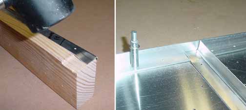
The above photo shows the "joggle" jig where you lay the "L" over the wooden step, and make a (hopefully) controlled dent in the end of the "L." This allows the "L" to lay flat over the longeron.
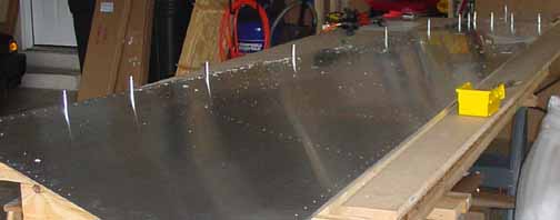
After each "L" was cut and joggled as needed, I primed the skin and "L" bottoms so that the diagonals could be drilled out to #30 and riveted. Since the diagonals do not interact with any other piece, they just act as stiffeners for the skins. (The vertical "L"s are in place above just make sure there is room for them as I drill out the diagonals.) I mostly work alone, so I wanted to get the skins some support as soon as possible. This freed up a bunch of clecos, too.
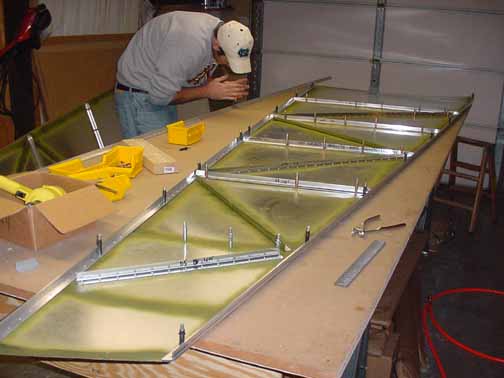
Here is everything all drilled out, deburred, primed, and ready to go. Now, I need to make the right side. Since it is fabricated just like the left one, there aren't any really any photos needed.
Jump to 2nd page Jump to 3rd page Jump to 4th page
![]()
![]()
Images on this website are either Copyright Zenith Aircraft Company and used by permission or are copyright Gary Liming