

Instruments Page 2
February 28, 2002
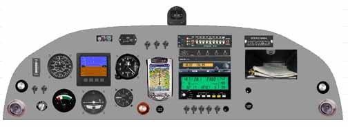
Just moved a few things around to keep my scan up and out. I added a cylinder select knob for both CHT and EGT next to the monitor, and decided the voltmeter and ammeter built into the monitor is enough. Aldo, I think I will need a slightly smaller box than the one Van's sells. I think this might be it.
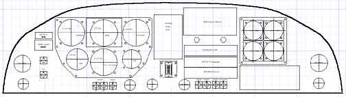
Here is the panel laid out in Turbo CAD. Pieces of it can be printed and used as a template for cutting the actual panel. The iPAQ will be surface mounted, so there are no holes for it, other than power and the GPS feed. A cold snap made it too cold to work out in the garage, so time to make a couple of the subpanels.
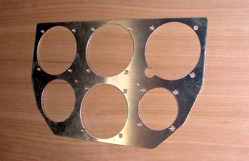
Above is the sub panel for the flight instruments. Lots of drilling, cutting, filing.
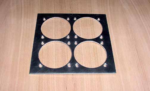
Subpanel for the gas gauges.
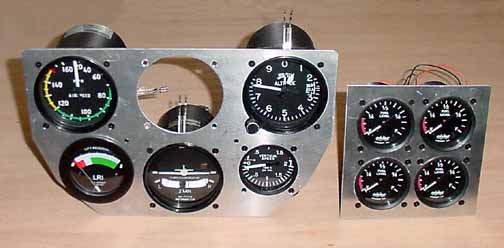
Couldn't wait to see some of the gauges in place. The white wires sticking out of the flight instrument gauges are the wires for some UMA lighting bezels. Likewise, the wires in the back of the gas gauges are for the internal lighting as well.
I will wait until the panel is installed in the cabin before cutting holes in it to make sure it retains its proper shape while drilling it in place. Once it is cleco'd in position, it will have the cutouts made.
March 2003
Well, already I'm glad I made subpanels, and sorry I did. I've decided to have a center console, just forward of the stick, and there will be the fuel valve and so I think the fuel gauges should go there as well, as the "both" position of valve will be part of the takeoff/landing checklist. See console for a picture of it. However, I've also decided that the flight instrument panel will be expanded to include the whole left side of the panel. Now, the instrument panel has some more space.
May 2003
One other component is needed to complete the picture - I need a dimmer for both the bulb type lights in the fuel gauges, and one for the UMA supply (which is actually a small inverter to AC) for the flight instrument bezels. However, since these are different types of supplies, it would be nice to independently adjust them on different channels, and then have them all slave to one master knob. Those kinds of power supplies are usually expensive and large, but lo and behold, just in time was an article in the June 2003 Custom Planes by Reinhard Metz about a kit that does just that. To see about the dimmer kit, click here. This dimmer circuit will be mounted on the fuse panel.
I've also decided to add a flap indicator. I know, many will think this overkill, since all you have to do to see where the flaps are is to look outside at the aft edge of the wings, but you really have to turn around to do that, and I don't think I like the idea of interrupting my scan like that in the pattern, and I am used to seeing the flap position on the panel. Therefore, what I did was:
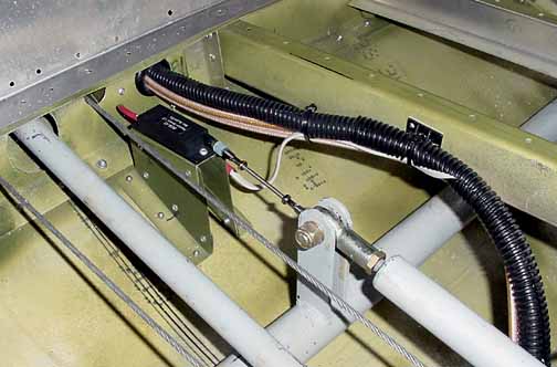
I mounted a position sensor (the ones from Ray Allen Company, same ones who do the MAC trim servos that come with the kit.) by making a U shaped bracket directly behind the flap torque tube arm. Right under the flap tube bolt is where the arm travel is just over an inch, so I drilled a 1/16th hole there and attached a clevis fork. The two clevis forks and the 4-40 threaded rod are from a R/C hobby store and work just fine. There is practically no resistance from the sensor, and the sensor I selected was the one with the 1.2 inch travel. The good news is that the sensor is only about $30, but the LED indicator that matches the trim indicator is about $70, so doing this with these components will set you back about $100.
Also in the picture above you can see the antenna and other wires coming from the aft fuselage. They are suspended by using a self adhesive cable tie anchor you can get at a home supply place in the electrical department, and they can be riveted or just stuck in place. The wire I used from the position sensor to the panel is just some 4 conductor 22 gauge braided (not solid conductor) telephone wire, like that used by the ELT. Now I can button up the rear seat.
![]()
![]()
Images on this website are either Copyright Zenith Aircraft Company and used by permission or are copyright Gary Liming