

Wings - 4th Page
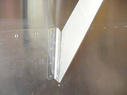
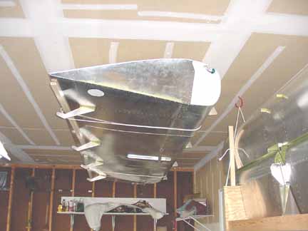
Last step is to apply the stiffeners to the flap brackets like the above, times four. That's it for the right wing. I have decided not to rivet either the I/B top skin or root top skin yet, since that would mean I can't easily get inside it afterwards. It only takes about 15 minutes to do it, so it will wait until final assembly. I have suspended the wing from the ceiling in my garage:
and will start on the right wing. I will only supply pictures of the construction of the right wing when there are differences, like the camera mount position, and the pitot tube.
Amazing how much faster the second wing goes when you are familiar with the territory and only have to look up to see a full size example! The spar and ribs and bottom skin went quickly.
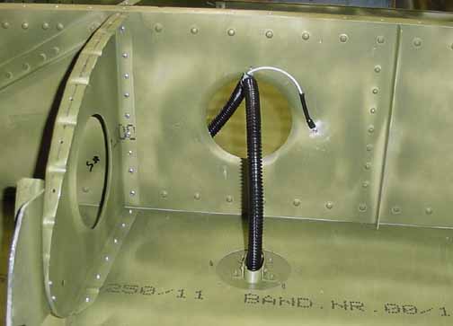
At this stage, the nose skin is just ready to rivet. Here, a ground wire is attached to the spar, and another wire is run through the black sleeve out to the root. Both wires are 14 gauge. Also inside the sleeve is the plastic tubing for the pitot tube. The pitot tube mount is just clecoed in place here, and its construction is shown on the instruments page.
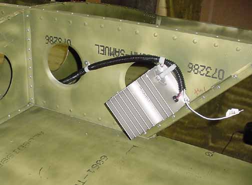
One thing I am doing differently than the right wing is to mount the strobe power supply before the nose skin is riveted. Here, everything is buttoned up and this was much easier. The white wire is to be connected to the position light when the fiberglass tip is installed, and the strobe wires plug into the white Molex connector at the top of the unit.
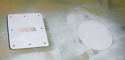
In the above, I cut back and drilled the probe mounting plate for the LRI indicator (described on the instruments page) and painted it, along with the camera port cover for this wing.
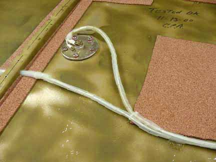
The above is the doubler that the LRI probe attaches to. Although you can't really see it in this picture, there are holes drilled in the corners of the doubler to relieve stress. The probe uses just two pneumatic lines - no electrical power, so its a snap to install. (You could add an optional heater, but since I've got a heated pitot already, I think that's enough. Besides, if the probe is iced, so the wing, therefore it's stall characteristics won't match the calibration anyway.)
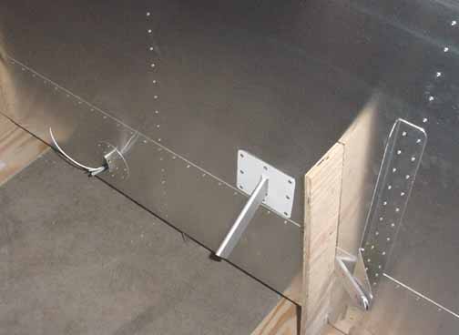
Above is how the probe looks on the wing. The wing is in the floor stands, pointed nose down. To the left is the heated pitot mount.
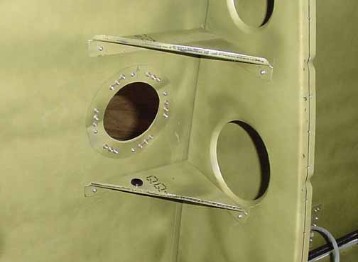
Above is the camera mount for the right wing - the doubler is identical to the one on the left wing, except this one is mounted near the center of the wing for a closer shot of the cabin. On the left wing, it was mounted near the tip so that the skin was fairly rigid, but here the mount was prone to some vibration, so I added these brackets to make the mount stationary. They also doubled as a stand-off support for the wiring - the grommet is on the lower bracket.
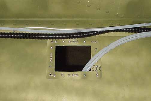
Above is how the tank sender wiring is done - the wires are wrapped some plastic spiral wrap and clamped with a nylon clamp onto one of the sender screws, and then a cable tie is tightened. Where the wires pass through the rib from the Aux tank, there is short piece of nylon 3/8 o.d. and 1/4 id tubing to keep the wires from scraping, The spiral wrap is also held in place with cable ties there. In the lower right hand corner, you can see the spiral wrap held in place with a dab of RTV silicon.
My son flew in to visit, and I took him back to the airport to load his plane at night. (He's a college student - he had lots of laundry.) The Cessna 172R he was flying has a nifty feature - it had small lights built into the wings that were switched. I am not sure if they were intended to be used in flight, but they were sure handy just loading luggage, looking for keys, checking the fuel color, etc. at night. They were located in the middle of both wings, just in front of the tie downs by the struts - they would allow you to check the landing gear while in flight, I suppose. I liked the idea, especially if camping under the wing, and realized my "camera mount" could serve just as a base for one of these. I stopped at a auto parts store and picked up bulb socket and some bulbs:

Above is the socket I got for a few bucks, and a long-life 10 watt bulb. Although the ones on the Cessna were dim (you can make all the jokes you want) they seemed to do the job, so I am going to try 10 watts. If that is too dim, I can always put something else in - that bayonet type socket is standard and has many different bulbs that fit it. On the left is the template I thought up and cut out of a file folder for the bulb bracket/reflector.
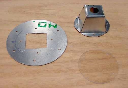
After a bit of fabricating, I made the plate with the square hole that has outer holes that matches the camera mount, and cut out a "lens" from some plastic left over from trimming a picture frame (about 1/16" thick) and I cut the sheet aluminum, drilled it, and bent it to form the reflector. The bulb just snaps into the 3/4 inch hole and allows the bulb to be changed easily. I will add a power socket to match the power line for the camera, and then I can substitute the light (with no drag penalty) if I don't want the camera. Here is the finished light:
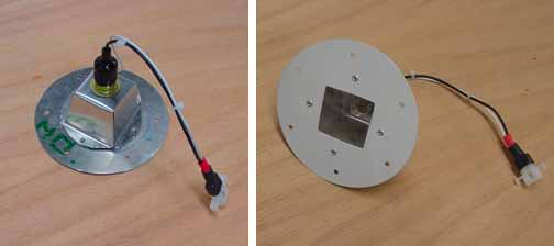
I added a ground wire and put on a matching plug for the power. Weight of the above unit, over the weight of the cover plate, is 1.5 oz. Now, the hole in both wings serves as either an inspection port, a light fixture, or a camera mount.
I was told that one of the purposes of a building log was to show that I personally built at least 51% of the plane (an FAA regulation for homebuilts) and to do that, I needed more pictures of me doing the work. Sorry about that, but I am going to need to include a few more of those in the future.
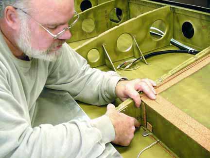
Here, I am placing the rear tank bracket in place to drill and rivet.
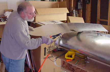
Cutting the curve for the upper root skin.
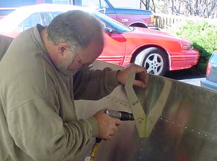
Drilling the positions for the right wing flap bracket stiffeners.
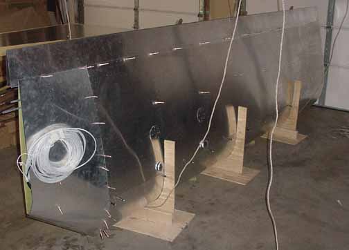
Finished wing ready to hang from the garage ceiling. Like the right wing, this one will wait until final assembly to rivet the center and root top skins in place, so it will be stored with the clecos as shown above.
Back to 3rd Wings Page On to Fuselage Section
![]()
![]()
Images on this website are either Copyright Zenith Aircraft Company and used by permission or are copyright Gary Liming