|
Welcome to the . . .
|
| Home |
Avionics - Flight Computer
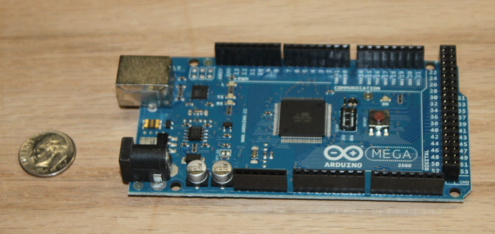
Fig. 10 Above is the Arduino Mega2560, which uses a Atmega2560 processor with an amazing amount of stuff built-in. The chip in the middle contains a 16 MIP RISC processor, 256K flash memory, 8K RAM, 4K EEPROM, (4) 16 bit counters, (2) 8 bit counters, (54) I/O lines, and (16) 10 bit A/D converters! Runs off of 7-12 volts and the active processor draws only 0.5 milliamps (not counting any sourced I/O.) On the lower left is the power supply socket and the upper left is a USB port for connection to the programming PC. Around the perimeter are pin sockets for "shields" which are auxiliary PC boards, made to fit this form factor, that provide application oriented hardware.
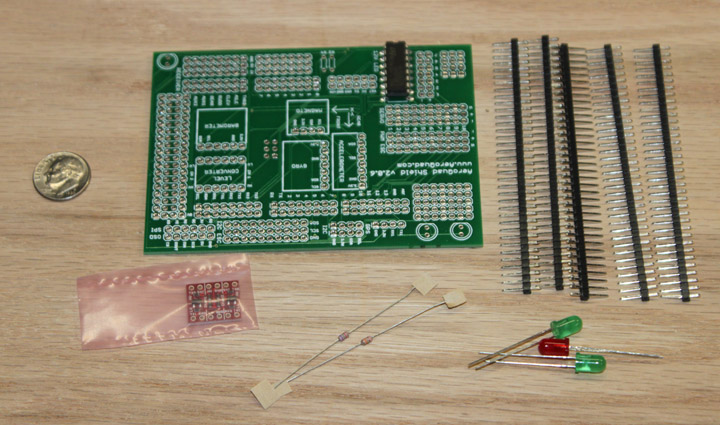
Fig. 11 Above is the 2.0 shield for the Quadcopter avionics, as it comes. A few components need to be soldered, as well as a lot of pin headers for the daughter cards. Some of the pin headers will be replaced with longer ones that allow the cards to be stacked.
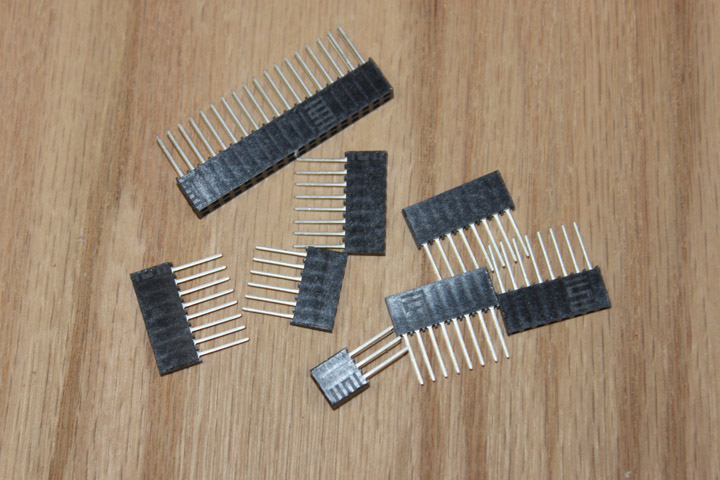
Fig. 12 Above is the header kit for the shield, allowing the pins of the Mega to pass through and stack the boards.
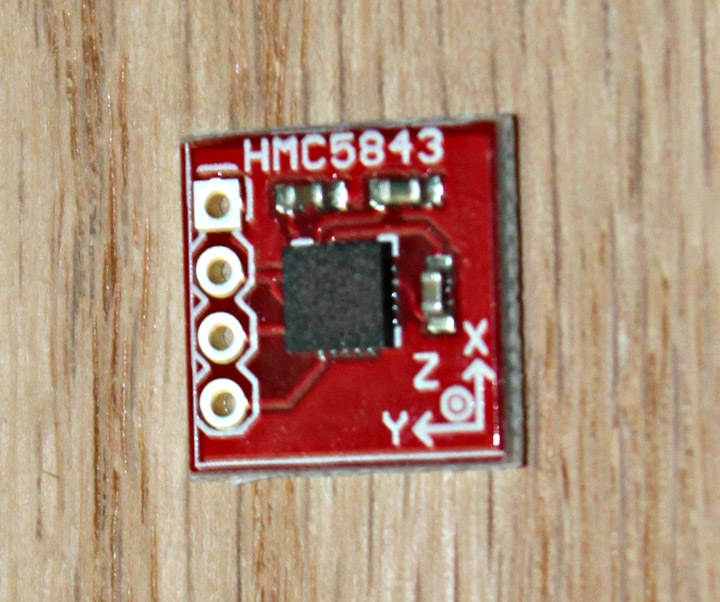
Fig. 13 Above is the Honeywell magnetic compass using an I2C interface, already SMT'ed to its board.
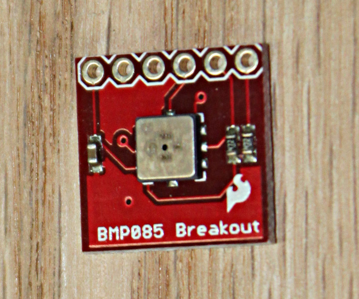
Fig. 14 Above is the BMP085, a high-precision, low-power barometric pressure sensor. The BMP085 offers a measuring range of 300 to 1100 hPa with an absolute accuracy down to 0.03 hPa. It's based on piezo-resistive technology with high accuracy and linearity, as well as long term stability.
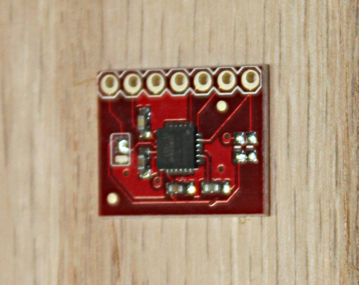
Fig. 15 Above is a daughter card with InvenSense's ITG-3200, a triple-axis, digital output gyroscope. The ITG-3200 has three 16-bit analog-to-digital converters (ADCs) for digitizing the gyro outputs, a user-selectable internal low-pass filter bandwidth, and a Fast-Mode I2C (400kHz) interface.
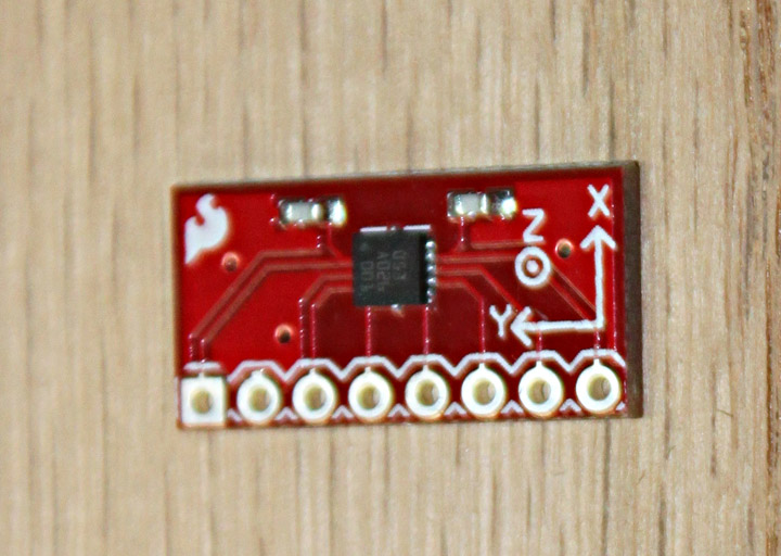
Fig. 16 This is a breakout board for Bosch's BMA180 three-axis, high performance digital accelerometer. The BMA180 provides a digital 14-bit output signal via a 4-wire SPI or I2C interface. The full-scale measurement range can be set to ±1g, 1.5g, 2g, 3g, 4g, 8g or 16g, snad performs a self-test on power up.
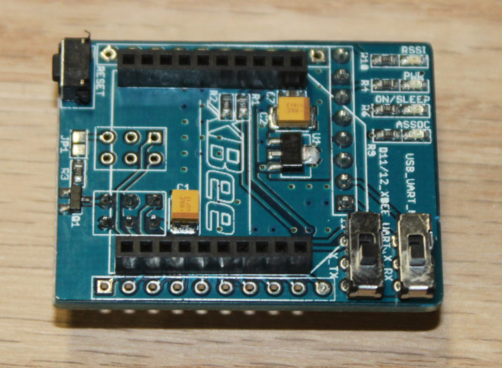
Fig. 17 Above is a daughtercard for an XBee RF transmitter/receiver to interface to the Quad 2.0 shield to provide telemetry to a ground station.
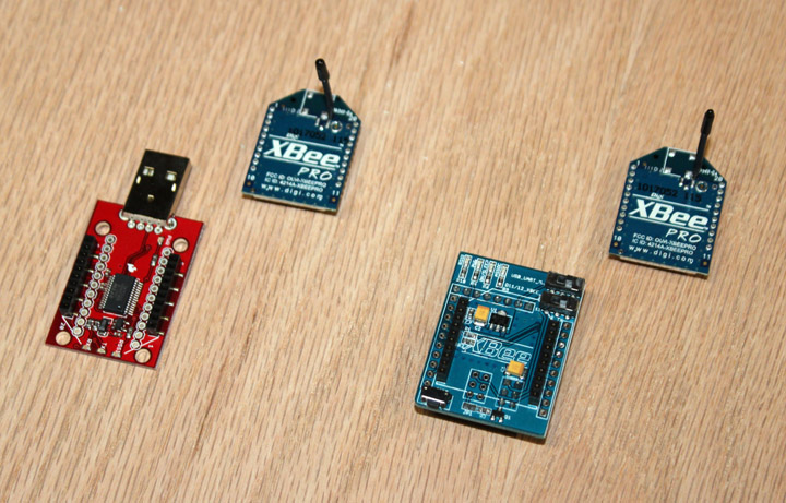
Fig. 18 Figure 18 shows the whole Xbee "suite" - on the left is a USB-to-Xbee adapter, with an Xbee 60 mW 2.4 GHz transceiver next to it showing a whip antenna. On the right is the Quad Sheild-to-Xbee adapter that has another Xbee transceiver that plugs into it. Together, these components constitute a high speed serial radio link between the ESPCopter and a laptop on the ground.
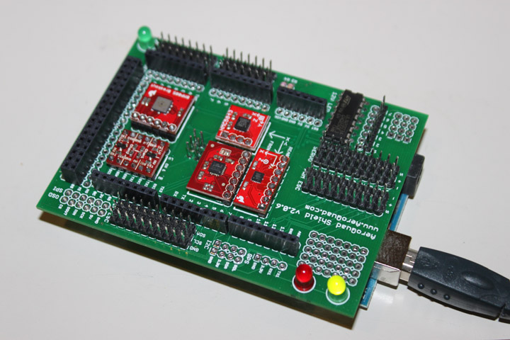
Fig. 19 Figure 19 shows the completed avionics deck for the 2.0 shield, with it plugged into the Mega2560 board underneath. It is plugged into a USB port for power and has the Aeroquad flight software downloaded and executed. The green LED on the lower right side is on, indicating that it's running. As shown, the flight computer (w/o the USB cable) is rather dense at 91 grams. The XBee components are not plugged in yet.
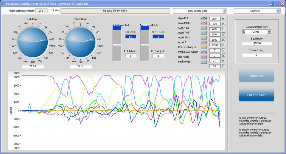
Fig. 20 Figure 20 shows a screen from the configurator that allows you to see the values being generated by the flight computer in Figure 19 as I move it about in the air. It is very interesting to watch how the values change with the gyrations of the board as I pick it up and fly it around. Making motor noises while doing so is optional. :^) |