|
Welcome to the . . .
|
| Home |
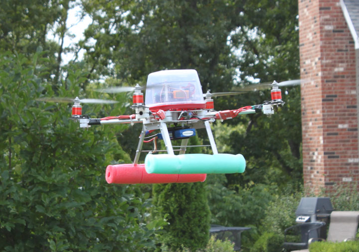
ESPcopter in flight. This website is a log of experiences in making a quad propeller driven helicopter for use as an aerial camera platform. The purpose of the website is to share information about building these aircraft, and to enjoy contact with others who have done so. Basic information about quad copters is available here. Nota Bene: The activity described here took place from the winter of 2010 to the summer of 2011. This whole area has changed so much since then, even becoming commonplace, but it was quite a new adventure back then and a great learning experience. When building these, there is already much shared information available to look over and evaluate. Out of several architectures available, I'm going to use the open source AeroQuad quadcopter implementation, which provides a code base written for several of the Arduino type processor boards, and a configuration utility written in Matlab for Windows. I can freely modify or enhance this code to support the existing components in a different fashion, or write and contribute new support for additional components. The main technology that makes these possible is a Proportional Integrative Derivative (PID) control loop for the four propellers. The feedback for this closed loop is provided directly by the momentum (inertia) sensors - the gyro, which provides the rate of change of angular displacement for all three axes, and the 3 axis accelerometer, which is used to correct the gyros. From there, flight control information can be inserted via a traditional R/C transmitter/receiver setup, as well as other means like GPS. Since it is the computer that actually controls the motors, and reads input from the "pilot" as to intent, this makes it a true "fly by wire" control system. The major components for the ESPCopter are the processor and its avionics sensors, the motors, the motor controllers, the remote control receiver, various camera options, and the battery to power everything. On the ground is required a remote control transmitter, and, of course, a battery charger. The Arduino processor cards come in different flavors to support different CPU chips. The one we've chosen is the Arduino Mega2650 which provides for the best expansion options. Arduinos have a built-in USB interface that is connected to a PC to download program images from the supplied Arduino integrated development environment under Windows. The planned avionics connected to this card will be an ITG-3200 - a triple-axis, digital output gyroscope, a Bosch BMA180 - a three-axis, high performance digital accelerometer, a Honeywell HMC5843 - a 3-axis digital compass, a BMP085 high-precision, low-power barometric pressure sensor, and a GPS receiver to provide positional navigation. This ought to be an interesting project! |

