|
Welcome to the . . .
|
| Home |
Frame The frame for the ESP Copter must be capable of supporting flight, maneuvering, and provide a steady platform for camera work. While parts are on order, frame development can begin. Although a quadcopter can be made quite small, this one will be about 24 inches in diameter in order to provide as stable a platform as possible while still keeping it relatively light.
Fig. 1
Fig. 2
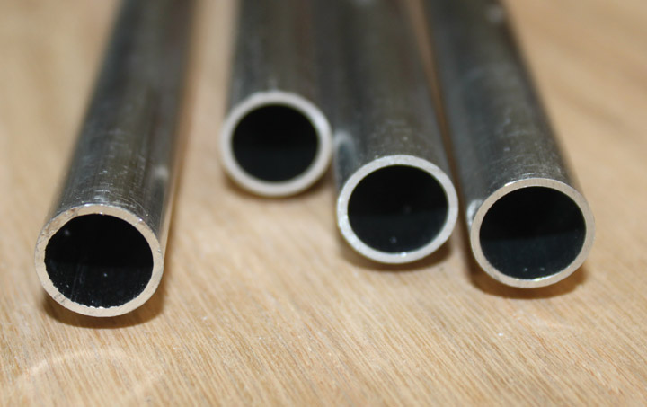
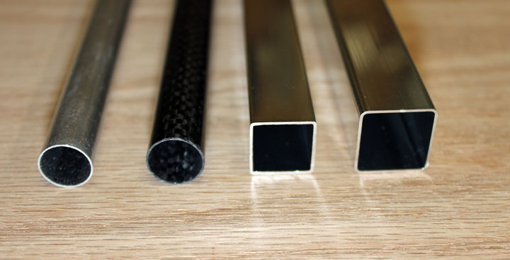
We'll start with the arms that supports the motor on one end, and ties into the frame on the other. Figure 1 shows some 6061-T6 alloy aluminum tubing, 0.5 inch OD by .032 wall that will be used to form the arms to support the motors. It weighs 28.3 grams/ft. and has a very stout feel to it. Given a 24 inch diameter machine, the total weight for these arms should be around 113.2 grams. Figure 2 shows some alternatives to this. On the right is some of the same OD tubing only with a wall thickness of .016, which weighs 12.7 grams/ft, or 50.8 grams for the four arms, just less than half. However, this tubing flexes under pressure of only a few pounds, and would likely take a bend even under modest crash conditions. Next is some carbon fiber tubing I found on Ebay that sells (2) 24 inch carbon fiber tubes for $20. They are only 9.5 grams per foot, which would be a total of 38 grams for CF quad arms, a reduction of 75.2 grams or 66%! The CF tubes have slightly different dimensions, being .544 inch OD and a wall thickness of .025. The smaller square profile is the "towel rack" tubing used on many copter frames that I got from Home Depot (SKU # 79171850240) for $3.49 for a 24" piece as a replacement towel bar. The four 12 inch arms can be made from just 2 of these, making it the price/performance leader by far. In fact, other than the nuts and bolts, these would be the cheapest parts on the quad! The tubing is .625 in square (15.88 mm) with .027 (.72 mm) walls, although the wall thickness varied quite a bit on the same piece. Weight is 34 grams/ft. (Note from the future: After trying the round arms (I think I was subconsciously concerned with aerodynamics, or perhaps just looking sleek, which doesn't really apply much here) with the clamps shown below, they add weight that square tubing doesn't require. There will be another square arm version next!) The one on the right is from Lowe's, which I heard also carried them. (SKU #0042378, $13 for a 24 inch towel rack, throw away the mounts.) This square tubing is .740 (18.75 mm) inches square with walls .025 (.66 mm) inches thick This weighs 40.3 grams/ft, so its pretty heavy overall. I had heard Lowe's carried these, but I didn't see the smaller one, and they didn't carry just the replacement bars. Once I feel I have good control of the frame, subtitling the thinner tubing might be a good way to increase flight time by lowering the weight. The clamps make swapping them out a snap.
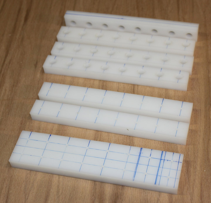
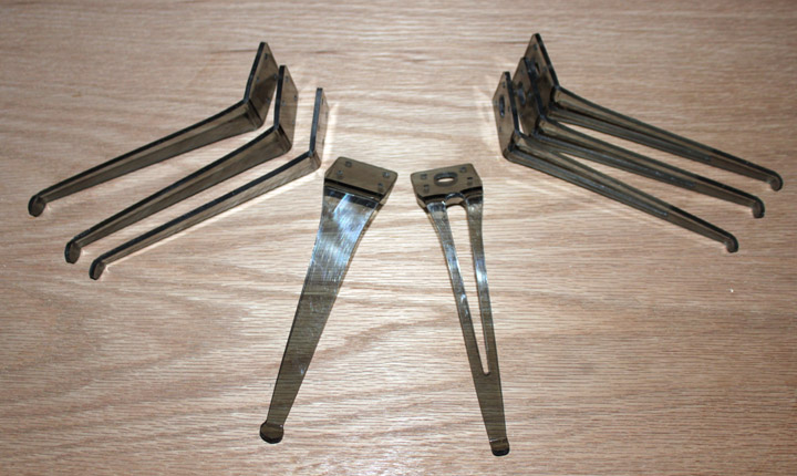
Fig. 3 Using round tubing will require some fittings to allow them to be clamped to the frame and motors. Above are some 3/4 inch thick slabs of UHMW (ultra high molecular weight- means they are tough, not heavy) plastic to make these clamps and motor mounts. These were easiest to make by simply doing the layout and a drill press, starting with small holes for placement and larger ones to full size. The bottom slab had been laid out, and pilot holes drilled using a jig to ensure uniform placement. The next one has been sawn down the middle using a thin kerf blade and sled, and the top four pieces have been drilled to final size to accommodate the arms.
Fig. 4 All of the above pieces of UHMW were drilled, then sawn to the above unfinished state (needs a little filing) to form a clamp around the tubing. The clamp as shown above is 11 grams; each arm requires 3, so total weight of the clamps for the copter frame is 132 grams. This weight could be saved by simply using square tubing which can just be bolted in place between the plates, so I will keep that in mind if the weight becomes an issue.
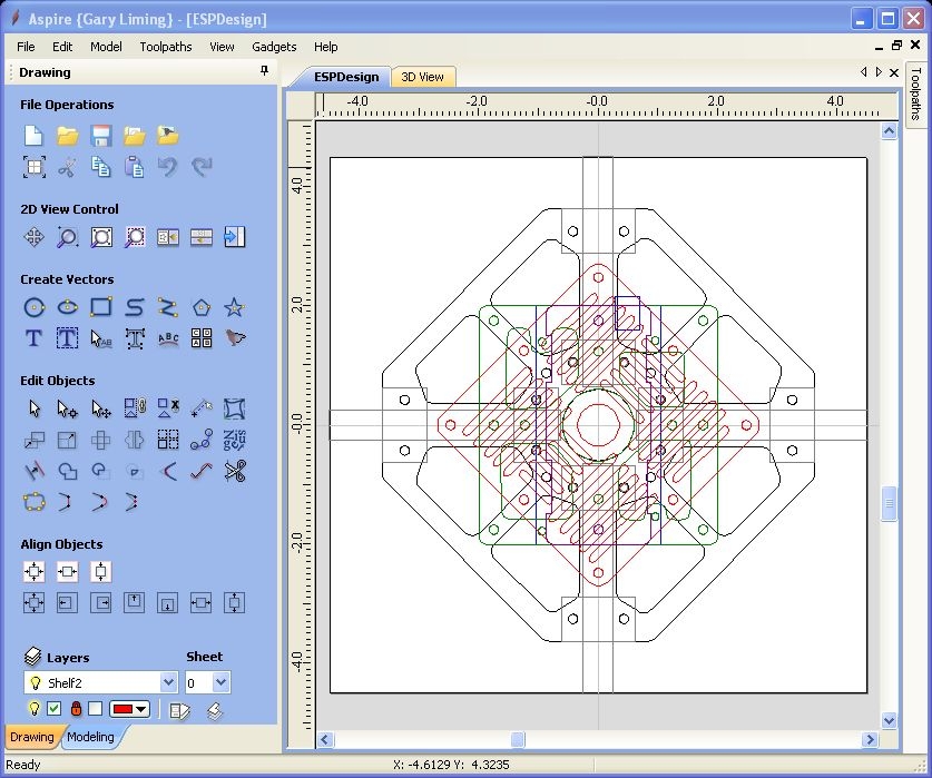
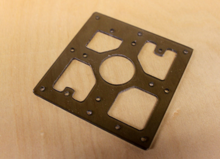
Fig. 5 The next step is to make the upper and lower plates to tie the arms together. These will be made of 6061-T6 by .063 plate, and CNC'ed to provide accurate hole placement and lightening holes. Above is a design for those plates which also shows the arms and clamps, and a shelf for the Arduino and how the Arduino is placed on it. This was done in Vectric's Aspire CAM software, which is a real pleasure to use and demostrates the power of doing each part in individual layers.
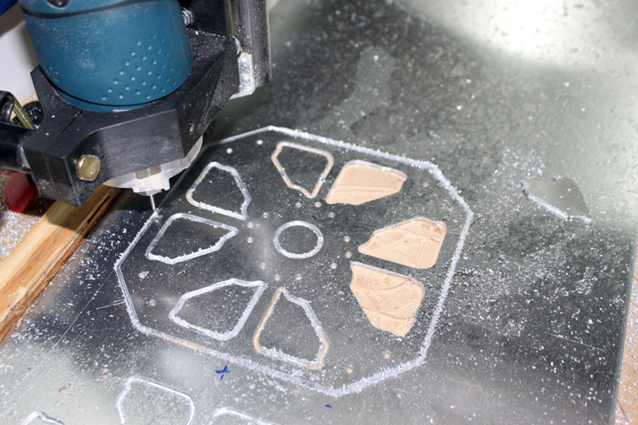
Fig. 6 Above shows the CNC machine cutting out the base frame plates shown in the drawing above. The plates ended up weighing 69 grams per, or 138 for both.
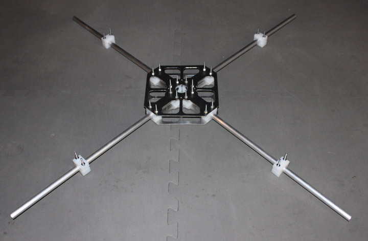
Fig. 7 The base frame plates have been bolted together with the arms and clamps using 6-32 hardware. The arms are 18 inch lengths of tubing shown in Figure 1, and the opposing motor mount clamps above are set at 24 inches apart. The arms will be cut off when a better idea about the effect that their length has on stability can be verified. So far, the frame, including just the arms, clamps, and plates, is at 383.2 grams, or 13.46 ounces. It still needs several things. Fast Forward a bit! After getting the ESCs, assembling the basic frame as shown in Figure 6, and seeing how everything might fit, it seems that there is still plenty of room if I shrink the plates a bit. Also, after looking at the power distribution problem, I decided to make the bottom plate with a mount for it in the protected center, so they are no longer the same part. The plates went from 68 grams each to 56 and 58 grams, a savings of 22 grams, shown below in Figure 8.
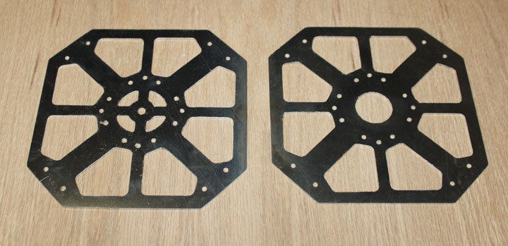
Fig. 8
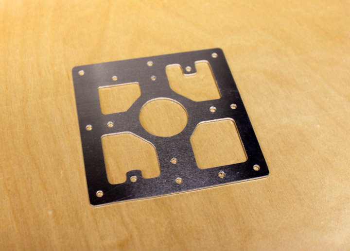
Fig. 9 One of those things needed is a shelf for the flight computer. Above is a design meant to accommodate the hole pattern it needs. It is 6061-T6 at .063 and came out at 26 grams. Since the FC is mounted with standoffs and 6-32 hardware, there is really nothing very structural about this or the remaining shelves. Maybe I'll cut one of these out of Lexan and see if there is any weight savings.
Fig. 10 The same shelf, only in tinted .125 Lexan. Now it's 21 grams, not much of a difference in total, but 5 out of 26 is almost a 20% reduction - I'll take it!
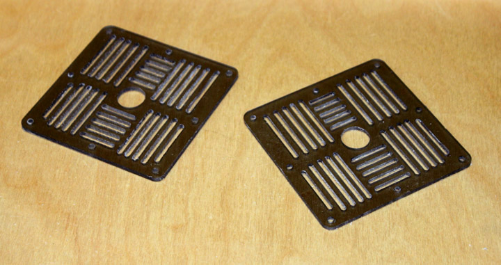
Fig. 11 Above are two Aux shelves to provide a mount for other components as well as perhaps some future ones. (They are made of the same Lexan as in Figure 10, and are fresh off the CNC - they need a bit of deburring.) The design is borrowed from the open source Arducopter, although size and spacing has been changed so that they may be CNC'd using a single pass of a .125 bit. The pattern makes it lighter and provides for good flexibility in accommodating future devices with different hole patterns. These weigh 23 grams each.
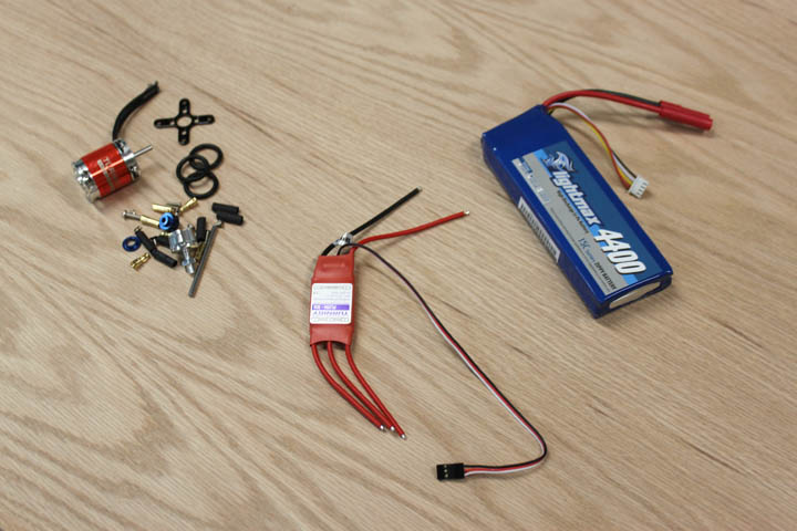
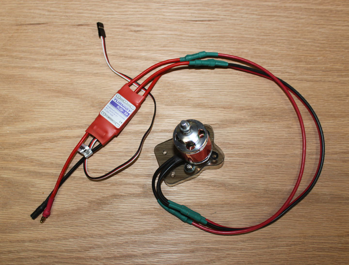
Fig. 12 The main motor components: On the left is one of four motors and the parts that came with it. Its a brushless "outrunner", which means the whole body spins and the center is bolted to the frame, like the old rotary aircraft engines. It weighs 71 grams and draws between 6 and 17 amps. In the middle is one of 4 ESC's, or Electronic Speed Controller which provides speed control for the motors on command from the flight computer. On the right is a 4.4 amp hour Lithium Polymer (LiPo) battery, providing 3 cells at 11.1 volts nominal.
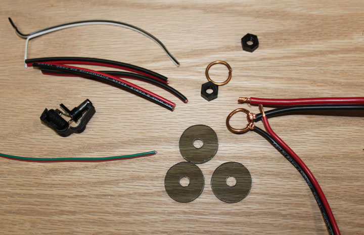
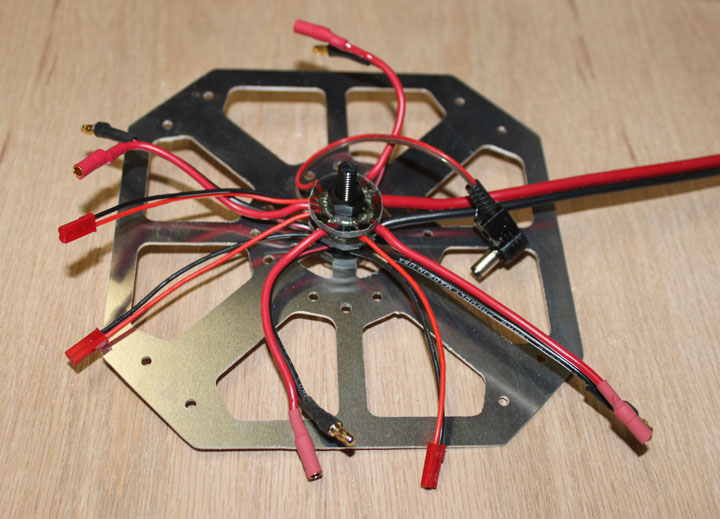
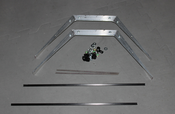
Fig. 13 One of the frame challenges is to make a distribution scheme for the power that doesn't look like a rat's nest. The LiPo battery needs to be connected to the ESC's, the Arduino, a battery monitor, Nav LED's, and perhaps another feed for outboards holding future FPV cams, OSD circuits, etc. I don't want to have to revisit this problem, so I will put on some expansion connectors. Figure 13 shows the parts - two hubs made from some 12 ga Romex type solid copper wire, one positive and one negative, a 12 ga stranded wire to the LiPo, the four 16 ga ESC wires to be soldered onto the hub, a 2.1 mm right angle power connector for the Arduino, three Lexan discs to insulate the hubs, and two 1/4-20 nylons nuts to hold it all together with a nylon bolt, not shown here.
Fig. 14 Above shows the ground hub wires soldered, and the power plug for the Arduino in place and JST type connectors on the other leads. The thicker wires to the ESCs will get 3mm bullet connectors. A 1/4-20 nylon bolt goes through the ring, with the Lexan insulators on either side.
Fig. 15 This is how it goes together - the positive and negative hubs have been soldered, three layers of Lexan placed between them, and bolted to the bottom plate with a nylon bolt and nuts. The ends of the ESC power wires have their bullets attached with some heatshrink. Total weight of the harness, including everything shown above minus the bottom plate: 53 grams.
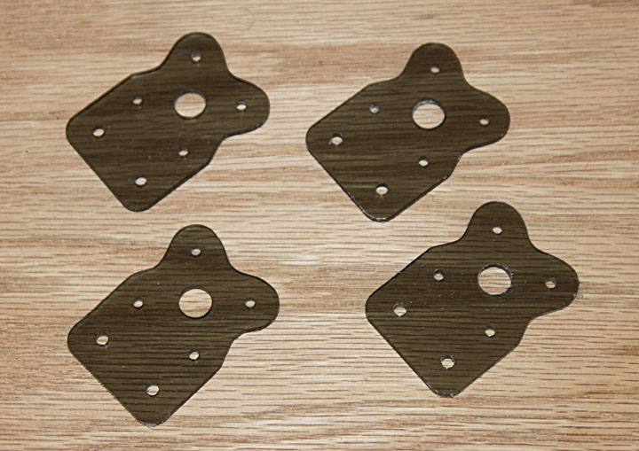
Fig. 16 Above is my first shot at a motor mount, also made from .125 Lexan. If there is any need for further reenforcement after making some tests, I'll take a look at it then. Many copters I've seen provide even less support than this.
Fig. 17 Above shows the motor power extension wires - each ESC has 5 3mm bullet connectors, and each motor has 3 and the three wires has 6, which is a lot of bullet soldering, times 4 for each arm. The length of the wires are just enough to slide out to change out the motor, and slide back in to the center of the frame. If I were to do it over again, I would have staggered the connectors by about half an inch so they don't all bunch up in the arm tube at the same spot.
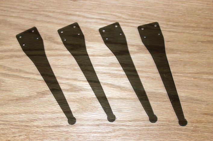
Fig. 18 Above is some simple minded landing gear made from Lexan. Lexan has the property that it can be be bent like sheet metal with minimal fatigue if proper bending radius is observed, so each of the above pieces will be bent a bit to form landing leg under each motor.
Fig. 19 After weighing them, I tried another version after removing some of the material. The ones in Fig. 17 are 11 grams, the ones with the holes above, right are 8 grams. These were bent on a brake to control the bend radius to prevent fatiguing, using a setback of .300 and a nose of .125.
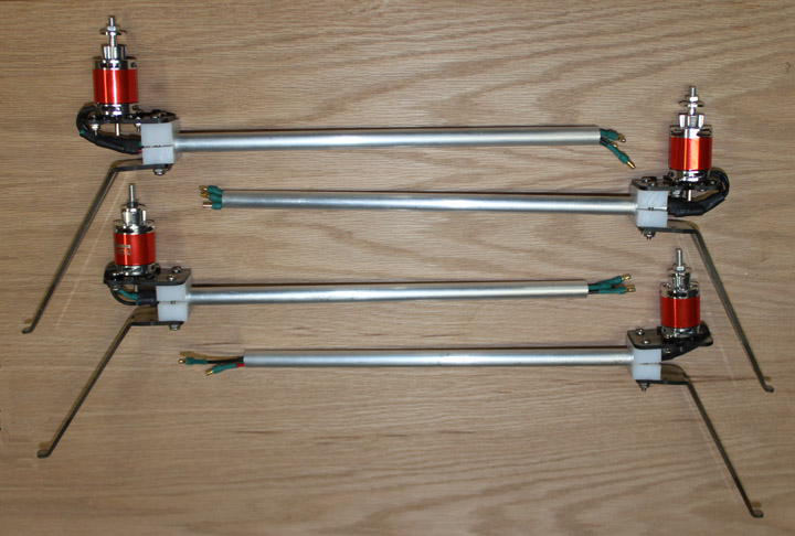
Fig. 20 Above shows the arm subassemblies. Motor direction is determined by swapping any two of the three wires in each arm. After thinking about it, I weighed the 13 inch wires from the ESC's to the motors at 9 grams each, or 108 grams for all twelve wires. By mounting the ESCs on the top of the arms and turing the motors around, I can save that weight, even though it won't look as clean. Since sleek aerodynamics are of smaller consideration than stable fight time, I think that is what I will do for now.
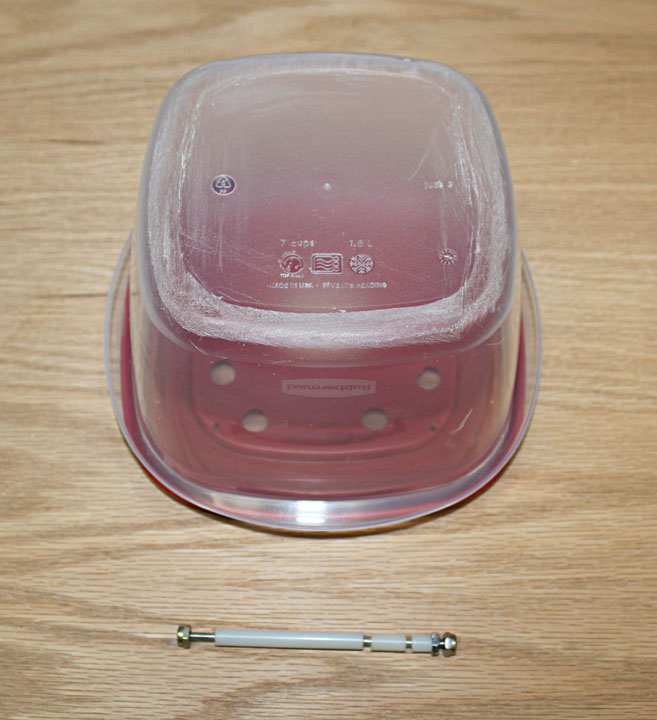
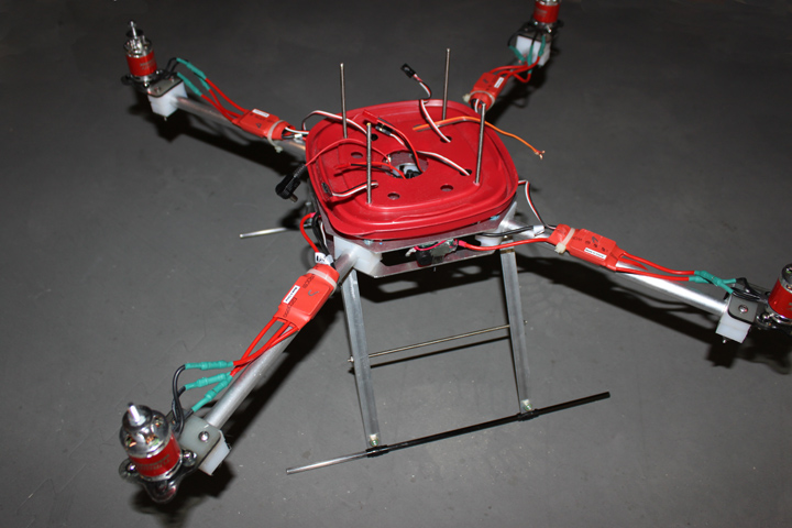
Fig. 21 Above is the shell to protect the FC. It took many trips to various places to find a container like this that fit well, but it sure beats manufacturing something! Although they all seem like soft plastic, several thinner containers cracked upon drilling. This 7 cup sized container weighed 140 grams. Under it is a corner column that supports the avionics stack. It consists of a lock nut and a jam nut on the right between which goes the upper frame plate. In between the gap of the next 2 spacers resides the lid shown above, and the FC shelf goes in the next gap. The long spacer is for the FC boards themselves, and the auxilliary shelf goes between the long spacer and the locknut on the left. The spacers are cut from a 4 foot length of hard nylon tubing, and the threaded rod is cut from 6-32 stainless steel, both from McMaster Carr.
Fig. 22 Ok, the Lexan landing gear was tried and didn't work - these copters are just going to be too heavy for that approach. With four props pointed down, ground effect is a real problem on landing, and it is easy to plop it down that last foot. One of the Lexan legs broke. Perhaps a smaller copter could use those, so I tried another design, shown above. Aluminum legs, carbon fiber skids. It's heavier than the Lexan legs by 100 grams (the same amount I saved by not running wires), but much, much stronger.
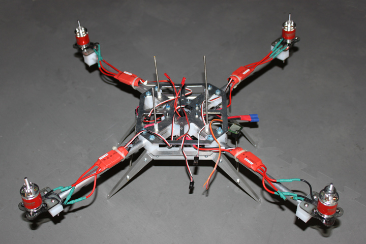
Fig. 23 Now, the frame is built up on these new legs, and looks like above. ESC's are zip tied to the arms. Once motors are running and proper direction is confirmed, I'll add some heatshrink to tidy up the wires a bit. Needs the skids and the base of the "dome."
Fig. 24 And here it's ready for the avionics stack. Between the plates on the side facing you is a battery monitor.
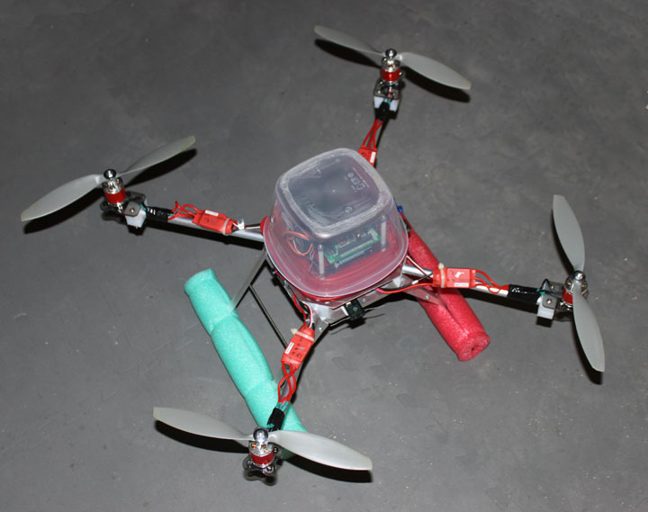
Fig. 25 Above is the copter ready for its first flight. Wires are taped to the arms. Pool noodle has been added as "training wheels" to lessen the shock of learning how to land well. Marine/Aero navigation light convention is used here - red is on the left facing forward (port side.) Ready to fly weight, including the weight of the 324 gram 4400 mAH battery, is 1876 grams. (1552g empty weight - I already know there will be another version that will be lighter, but this is not a bad start.) Mounted are some 10x3.6 props to start. After I get a feel for them, I'll put on some 11x4.7 for comparison of flight times, etc. Yet to be added is a 2 axis camera stabilized camera mount, and a FPV camera xmitter and power supply. |