|
Welcome to the . . .
|
| Home |
Tuning This page is to describe and illustrate the process of final assembly, testing, and tuning of the whole copter system.
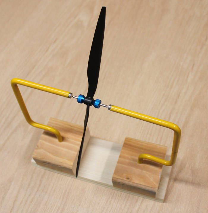
Fig. 1 While waiting for the order from Hong Kong (zzzzz........) I made a couple of things that look like they might be useful. One importantant job is to make sure the props are balanced. Above is the balancer I made from a design I saw on the Aeroquad forum. It consists of a couple of ladder hooks screwed into some scrap wood with enough height to clear the largest prop you might want to balance. The tips of the hooks have been cut off and rare earth magents have been fixed to the ends of the hooks. Then, a Great Planes finger prop balancer ($4.49) is inserted between and suspended by the magnets, providing a near frictionless pivot that allows any weight difference in the blades to be quickly visible - the slightest air current makes the prop spin. The prop is then lightly sanded on the back, thicker part of the heavier blade until neither side wants to dip down. (The idea of using the garage hooks I got from Dave Packham. Thanks, Dave!)
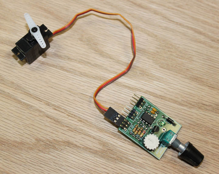
Fig. 2 Also, I wanted to start playing with servos, so I bought one of these as a kit and assembled it. It just produces the pulse needed by one (or two) servos, timed by its knob position. A battery connects to the middle pins, not shown. Useful for checking status and range of servos.
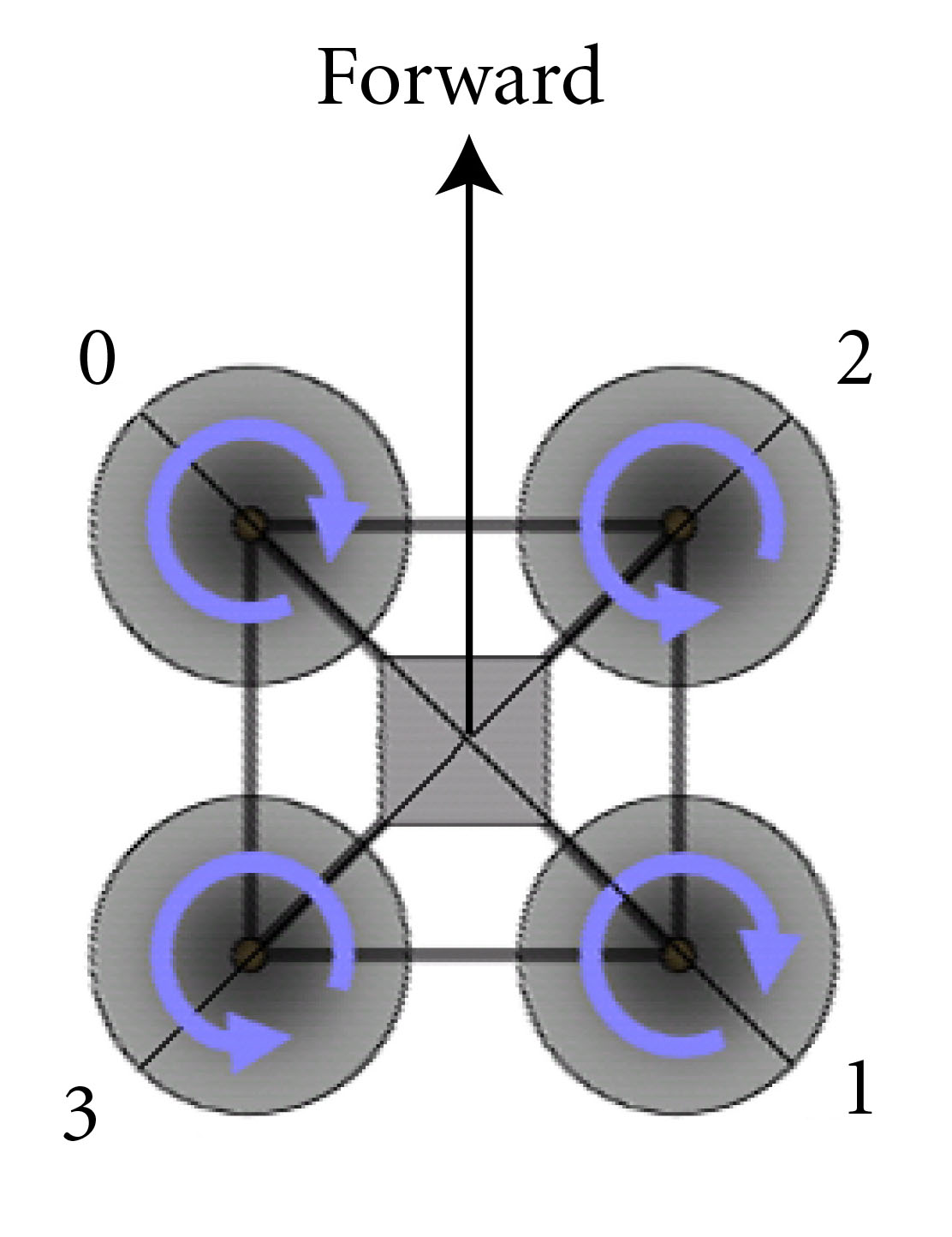
Fig. 3 Ok, once the frame is built and everything is wired, we are ready to configure the copter. Before applying power to the copter (this is true each time you power it on) make sure the copter is level - when the system powers up, it accepts the gyro readings in that position as level flight from then on. When the FC is powered up with the code options selected, compiled, and loaded, connect the FC to a PC via the USB cable and run the configurator - its version must match the code that's been loaded in te FC. The first thing to do in the configurator is make sure the EEPROM on the FC is intialized by selecting this function in the configurator. This must be done each time a new version of the code is compiled and loaded. Next, without the motors powered, test the radio control by moving the joysticks and switches for each channel, making sure proper direction and full range of motion is correct. The next thing to do is calibrate the ESCs, which is done with the motors powered, but without props mounted, and following the procedure given in the configurator. This step informs the ESCs what full range on the controls looks like, and allows the ESCs to drive the motors within that range. The next thing to do is make sure the motors are spinning in the right direction, as shown in the above diagram. By applying just a bit of throttle (without the props mounted!), you can see which way the motors are turning. To reverse direction, simply swap any two of the three wires between the ESC and the motor. Once this is done, you shouldn't have to do it again unless you swap out motors. Figure 3 assumes the copter will be flying in the X configuration, (forward is between two motors) and not the + configuration (forward is in line with one of the motors.) The next step is to see if the gyros are working - without props, apply some throttle to get the motors moving. Then, tilt the copter to one side. The motors that are tilted down should spin up on their own to compensate, and the ones on the opposite side should spin down. Do this for all axes. Then, with the copter level, provide some right movement (aileron input) with the stick - you should likewise see some left motor rpm increase, etc. Do this for all axes as well. Now, we can mount the props and give her a go! |