|
 Making the mobile base |
| Home Page |
This page describes building a mobile base for InMoov.
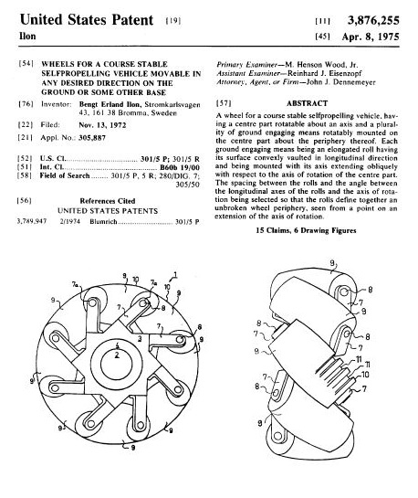
Fig. 1 Although everyone wants to see a full size android with humanoid legs walking and running (and that is being worked on) so far legs are still in development. For now, it is a far easier problem to mount the InMoov on some type of mobile base in order to move it around conveniently. After looking at some robotic platforms, there are some that use omnidirectional wheels that allow the base to move in any direction without turning, or allow it to turn with a zero radius. These are sometimes called Mechanum wheels, but they were invented by Bengt Ilon of Sweden and he was granted a U.S. patent ( No. 3876255) in 1975, shown above.
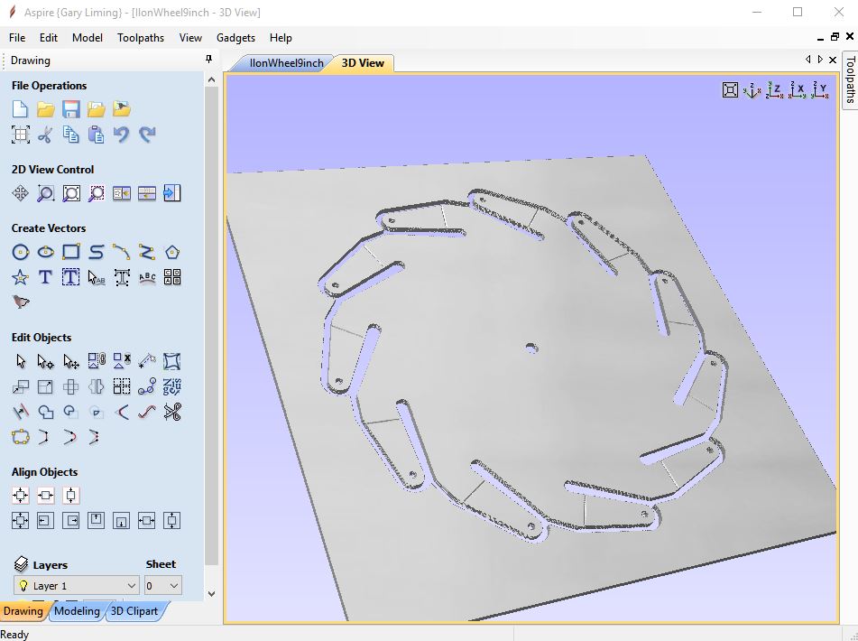
Fig. 2 I saw on the InMoov community page where maker Markus Örngren in Sweden was not only using these for his InMoov, but printing them from Thingiverse as well. It seemed to me that the rollers at least would be great 3D printed items, but I wasn't so sure about the hubs, so I started a design to CNC those, shown above, which would allow me to choose different materials. I think I will start with Lexan, as I have always been intrigued by its strength and toughness. I decided on eleven rollers on a 9 inch wheel to accommodate fairly large diameter individual rolllers which would provide a good balance between strength and smooth rolling. If these work out, I'll make the dxf files available as well. If the Lexan won't hold up, I can always cut them from aluminum.
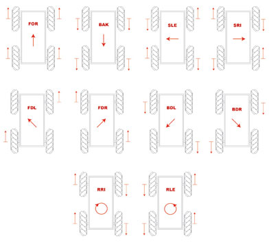
Fig. 3 The cool thing about these wheels is the enhanced motion that is possible with them. With simple forward/reverse motor commands on each wheel, 10 different motions are possible as shown in the diagram above that I did to keep the wheel directions straight in my head. The commands are FOR (forward) BAK (backward) SLE (sideways left) SRI (sideways right) FDL (forward diagonal left) FDR (forward diagonal right) BDL (backward diagonal left) BDR (backward diagonal right) RRI (rotate right) and RLE (rotate left). The last two provide a zero radius turning capability. The diagonal movements are achieved by keeping two motors off, so their movement will be at half power. I am thinking of translating these commands into a MRL service that are passed by script along with duration and or amplitude (speed) to an arduino in the base that then talks to the motor controllers. I think simple DC gearmotors will do fine here, and the batteries to drive them will help stabilize the robot.
Fig. x Here are the motors I will try, 12V DC 30 RPM gearmotors, that I got here. They are fairly good quality motors that appear to have quite a bit of torque on them rated at 14Kg/cm. The 12V means a different battery, but since this is just for the base, and just moving it around will need some power, having an SLA battery in the base separate from the rest of the robot's power makes sense. I will connect the base arduino to the robot's main cpu as well as have it take manual directions from joysticks. Also, on the right is one of two dual motor drivers I will try, although I am not sure they will handle the power needed, but they are rated @ 25 watts. I got those here. Fig. y Above shows the analog joysticks and their printed mount that will control the base movement manually. The each stick is given +5 and ground, and two wires then return with a voltage between +5 and zero for X and Y that feeds 2 of the Arduino's A/D inputs. There is also a wire for a switch that toggles from +5 to ground when the knob is pressed down if you want to use it as an additional digital input. Comments may be directed to gary at liming daught org. Thanks for viewing this build log! |