|
 Making the head |
| Home Page |
This page describes building InMoov's head.
Fig. 1 This place reserved for completed head.
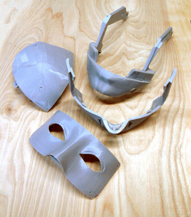
Fig. 2 The Autotroph printer I am using has quite enough print volume to print the larger combination variations. Above, the upper lip (the piece in the middle) is usually two pieces joined at the nose which I printed as one for added strength. Likewise, the right front skull (the piece on the upper left - "Left+right front skull no holes" by zazics) is usually two pieces, but I printed the variation whole. Actually the whole front of the skull (normally four pieces) is available as a single variation and would easily fit on the print table, but the slicer said it would take 13 hours to cook, so I didn't want to push my luck quite that far. Also, printing these parts whole means a fair amount of filament is wasted in printing support material for the overhang that is thrown away. The lower jaw and its hinge brackets shown at the top are three pieces joined by 12mm M3 bolts. Sometimes, due to the anisotropic nature of printed material (like the "grain" in wood) a better part does not result from printing a part as one piece.
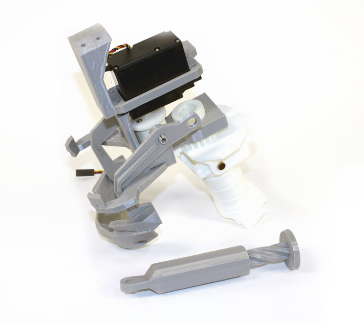
Fig. 3 Here are the neck parts. The base of the skull is hinged on the neck stem with some of the tubing used in the hand. I still need to place caps on the ends. The jaw is in place but there needs an additional frame to hold its servo. The larger servo, an HS-805BB, is used to rotate the head. In one of his comments, Gael remarked that he used this servo because he already had a frame for it done in Blender, but you could probably get by with a standard sized one. Adapter pieces are available like "InMoov Neck Rotation Servo Adaptations" by bstott that I will look into. I will try to do that, since this larger one is also used for the biceps as well.Below the neck assembly is the piston that is mounted on a servo in the torso that moves the head up and down on the brass hinge. The nominal jaw hinges "JawHingeV2.stl" have hollow split pieces that are just a bit too thin to support the jaw well - I broke one of them off just assembling the head. I substituted Keith McGerald's jaw with screw1.stl variation that allows for a screw and washer to be used to hold the jaw in place on a solid support.
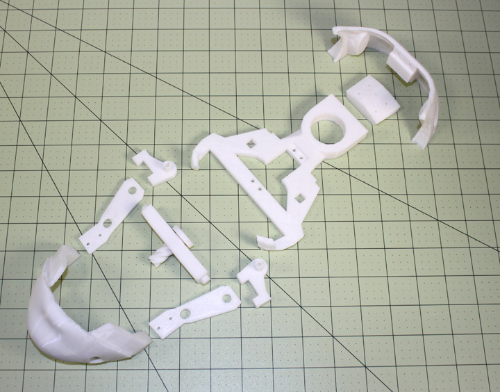
Fig. 4 I am almost at the point where I am reluctant to print anything since it seems like right after I do, someone puts out an improved design! Since I printed and wrote the above, someone else has solved the problem of using standard size servos for the neck rotation and the jaw movement. Norwegian maker Mats Önnerby completely re-designed the internals of the head to not only use smaller servos, but make more room for electronic components in the head. Except for the lower jaw, all the outside skull and facial pieces may be used as they are. Above are most of the internal parts that he designed that fits onto the existing neck hinge and pivot. Mats eliminated the neck gear, placing the servo in direct drive to rotate the head. This means the head is sitting on the servo with one end connected to the back of skull and the servo's output shaft on the neck pivot - the weight of the head is on the upper neck with the retaining ring holding it in place. The jaw needed to be changed to fit the new jaw support arms. The back of the skull was changed to accommodate the smaller servo attachment, but was done in two pieces like the original. I printed them in one continuous pieces by "welding" them together in Sketchup (this one-piece lower rear skull model is available on the download page.) The piston and its threaded bar were printed with a 0.1mm layer height to make it movement as smooth as possible. He also re-designed the eye mechanism for a smoother movement, described here.
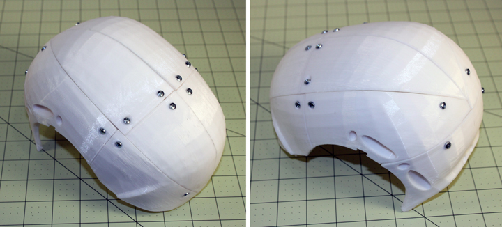
Fig. 5 I have to say that I am not too happy about the fit and finish of the skull, and the low poly count is much more pronounced than I thought I saw in other builder's photos, so it looks like I will need to spend some time with the epoxy and filler primers and then paint it. There are a lot of possible reasons for the poor fit, and since others have reported good results, it is probably something I did or did not do to cause some of the gaps. In the above photo, I am using some 3mm pan head screws I had, which is not the right kind of screw so they stick out too much. I will use them to hold the parts in place while the epoxy sets up, and then remove them, and begin work on filling and sanding the gaps.
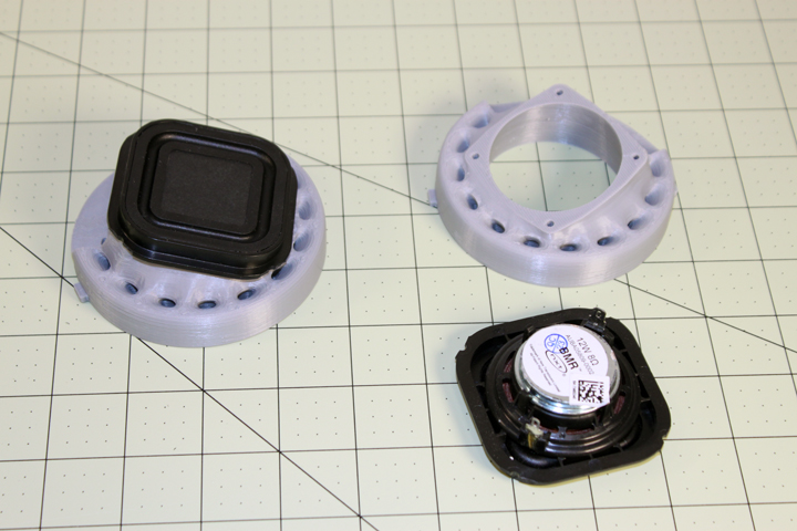
Fig. x The 2 inch speakers I am using are from here and are shown above, along with the mounts, EarSpeakerLeftV1 and EarSpeakerRightV1. They fit onto the speaker ear mount with a bit of sanding, and will simply be epoxied in place. For such a small size, they have a pretty decent sound. These speakers are 8 ohm, 12 watts and have a solid plastic cover over the speaker cone, also making them a bit more rugged. Comments may be directed to gary at liming daught org. Thanks for viewing this build log! |