|
 The Torso |
| Home Page |
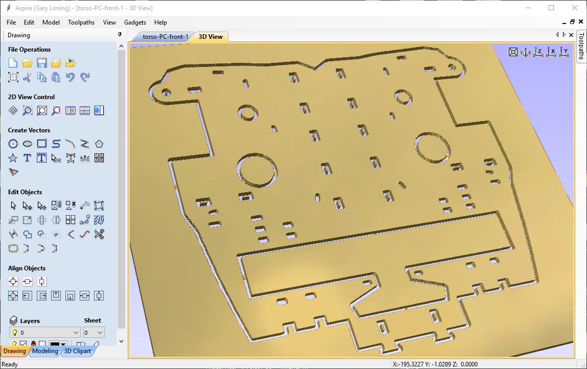
Fig. 1 The torso consists of a front and a back plate that are both made up of many smaller glued up parts, which of course is where the head and shoulders attach. Above is a simulation of the front torso plate that would normally be 10 separate 3D printed pieces glued together. One of my immediate thoughts was to use the designs to create a 2D drawing so that these plates might be CNC'ed. (I have a home-built CNC machine, shown here.) This way I can use a stronger material, like polycarbonate (aka Lexan) which is the material from which they make aircraft windshields and bullet proof glass. Really tough stuff, yet easy to machine. On the MRL forum, I found one of its members, zviangi, had the same idea and offered a .DXF file for both the front and back. These files produce the version of the torso plates that support having a Kinect 360 in the midsection, which I also plan to employ. However, just like 3D model files are not always printable if they are not manifold, or "watertight," 2D files may not be CNC'ed if the vectors are not joined into closed shapes. After spending some time in my CAM software (Vectric Aspire) I got the files with all the vector shapes in a closed format, like the front plate simulation shown above, ready to produce some toolpaths with which to cut the plates. I also found that some of the holes and circular shapes needed to be redrawn as circles rather than many adjacent arcs, and needed to be repositioned a bit as well. Both of the files I used are available on the download page.
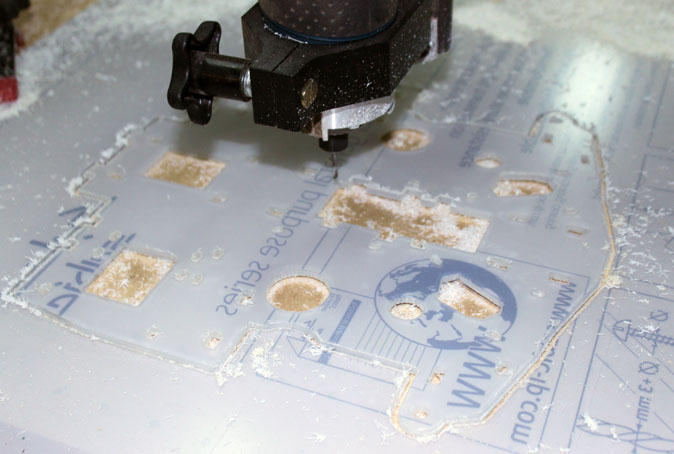
Fig. 2 Here the CNC router is cutting a torso back plate for testing. Since the router bit is round, it cannot leave a perfectly square inside corner, but I was using a 1/8 inch bit, cutting the material in 4 passes (or layers for you 3D guys) so the corners really only need a few swipes of a square edged file to make the corners sharp and square. The above is a trial cut from some thinner material to ensure the correct overall dimensions and to test-fit the holes into which other printed pieces will be attached. I did find that some of the holes and circular shapes not only needed to be redrawn as circles rather than many adjacent arcs, but needed to be repositioned a bit as well.
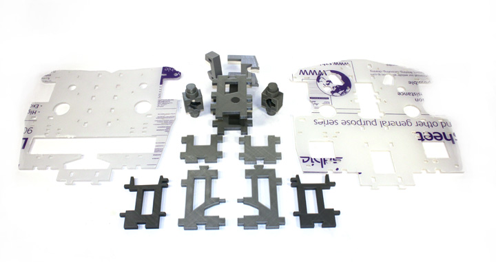
Fig. 3 Here are some of the printed pieces that go between the front and back plates. The top two pieces form a base for the neck attachment. The cage like structure just under them has a "servo holster" inside that houses the large servo used to tilt the head up and down. The bottom pieces are the Kinect versions. The front and back Lexan plates still have the protective film over them. The parts above represent a parts count reduction from 33 to 15.
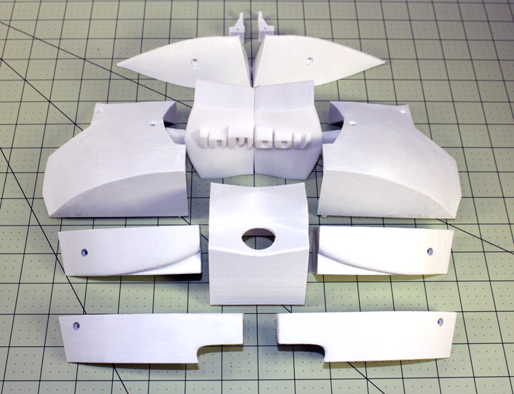
Fig. 4 Here are the chest parts just off the printer. This is the Kinect/PIR sensor versions from the nominal distribution. Not sure about the back pieces yet. Comments may be directed to gary at liming daught org. Thanks for viewing this build log! |