|
 Nervous System |
| Home |
This page documents the nervous system of the InMoov, i.e. how the servos and sensors are connected to the SBMs (single board microcontrollers) and how the SBMs talk to each other, and how they are all programmed. The are two basic approaches - one is to roll your own architecture and software, and the other is to use an open source robot control system. Using an open source robot control system has many advantages - ideally, it should allow others to share their work, so that each of us contributes a part to the whole picture, it should allow new users to save a lot of time by taking advantage of the past work, and if done right it should simplify the programming. When I first looked into this, there were a few open robot control systems out there, like ROS, EZ-Robot, and MyRobotLab. The one that looked like it was the most InMoov specific and had support of several InMoov developers (including Gael) was MyRobotLab (MRL), so I think I will start with that one. MRL supports using Arduinos which are inexpensive, has lots of shields and libraries, and have many form factors available, while EZ-Robot sells an SBM that has more functionality but doesn't provide support for custom development for it. Starting with the MRL/Arduinos will allow me to change my mind without a serious loss of investment if there is a good reason to switch later. The way MRL works is it assumes that the servos and sensors on the robot are connected directly to an SBM - an Arduino or some other supported SBM, and that the SBM's talk to a main PC running Java using one of several different types of serial links. The most common serial type is the USB acting as a COM port since almost all of the Arduinos already have one that is used to load their programming. The MRL Java distribution includes an Arduino sketch that is compiled and loaded into each Arduino which then can talk to the MRL Java application. In effect, this sketch turns the Arduino into a USB front end for the servos and sensors - i.e., the Arduino becomes an adapter for the servos that has a serial USB protocol on one end, and a bunch of servo and sensor connectors on the other. The Arduino accepts command messages from its USB link and moves the servos or reads and reports the sensors accordingly. All the decisions about when and where to move and what to read are done upstream on the PC.
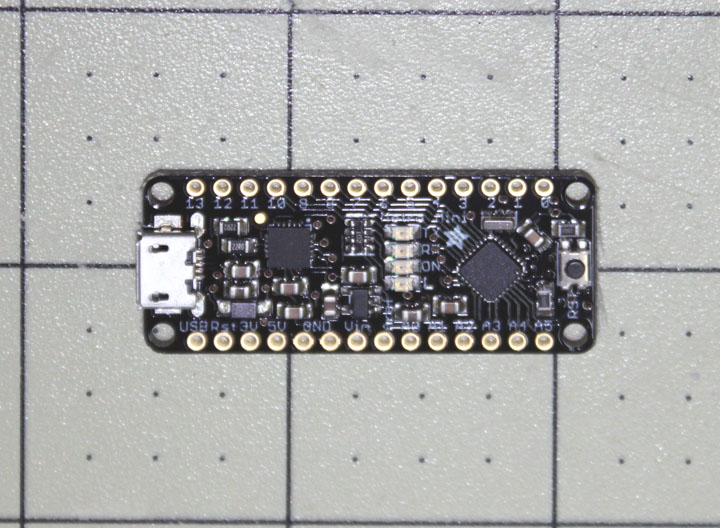
Fig. 1 This is a picture of the Arduino I am going to try out, Adafruit's Metro Mini. I chose this one for the simple reason that it has a small form factor (it is shown on one inch squares), but looks just like an Uno to its software. MRL supports both the Uno and Mega flavors of the Arduino, so this should work without modification. In fact, the only noticeable difference between the Uno and the Metro is that the Metro uses an FTDI chip for its serial USB interface, but that's a good thing anyway. The early Arduinos used this chip, but it was changed later and many of the clones use something else as well. If you don't have the FTDI Virtual Com Port driver installed, they have a well supported signed driver download for many different platforms that is easy to use.
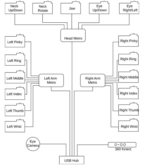
Fig. 2 This is a preliminary wiring diagram for the basic robot. Besides the 3 Metros shown here, there will be at least one or two more needed to drive the biceps, shoulders and waist but I am currently toying with the idea they should be steppers instead of servos. Each of the servos will be wired to Vcc (6 volts) and ground as well as the signal wires that go directly to the Metro pins. I will get a USB hub that can be modified to use its power supply to drive the +5 volts to the Metros and cameras. I'll have to see later about what the Kinect needs. The hub then connects to the main control PC, which will see a COM Port for each Metro, camera, and Kinect device. I will use my desktop PC as a test bed for a stand-based InMoov, but I am hoping there will be something small and elegant to embed in the robot when the time comes to make the machine more mobile. The nominal InMoov plan uses an Uno and a Mega for the SBMs, so by choosing to divide them a bit differently I will have to move some of the code around to get the correct servos on the correct Arduinos, but I am hoping that will not be too difficult.
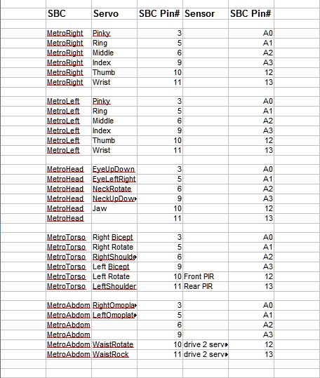
Fig. 3 Here is a preliminary table of which servos will go to which pins on which Metros that I will use as a guideline. Here I show 5 Metros if servos are used throughout, but I am unsure of which will be used for the torso and abdomen SBMs if steppers are used. I think I will get the arms and head working first, and then see where we are with the stepper idea. I've also allocated two pins on the torso metro for PIR sensors - one front, one back.
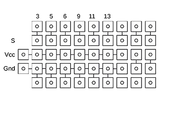
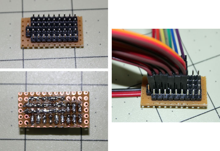
Fig. 4 The next problem is how to get all the wires for the arm servos connected. All of the servos need to be connected to Vcc (6 volts) and Ground, and the signal wires to the correct pins on the Arduino. However, I think it may be to my advantage to make the servos easy to swap out, so that means accommodating the 3 pin connector they all use. Whatever arrangement is employed will be duplicated to support both hands. To help support his work, Gael has come up with a Nervo board that essentially provides a wiring capability like this using the Mega/Uno scheme, but as of this writing, (August 2015) the boards were both back-ordered and the store was not taking orders. I would like to support Gael's work, but I think I will proceed on my own here and so I sent him some money directly that I might have some good karma about it. Figure 4 is the diagram for what I came up with. It is similar to one Chuck Fletcher posted in the MRL forum. It uses header pins soldered into a perf board and provides for the 6 servos named in Figure 3 with a seventh for expansion (the column next to 13), connectors for sensor inputs and an extra ground bus for them. The top row of numbers indicates which pin on the Metro is used, and the left most Vcc and Gnd pins are connected to the battery supply for the servos. The top row of pins are for jumpers that go to the Metro. The next row of pins are for the servo connectors inserted vertically. The next row is the Vcc rail, and the next row is the ground rail. The fifth row is a secondary ground rail. The rightmost 2 columns are for jumpers for sensors. This approach should be okay for the light weight servos in the hand, but the heavier ones draw more current than this wiring can handle. When engineering how big the wire should be to accommodate the projected current draw, it is always a matter of how much temperature rise you can tolerate on a continuous basis before the wire insulation melts or burns. Bundling the wires in any way makes it worse. Also, the smaller the gauge wire, the higher the resistance it presents and the more power will be lost going to the motor. In this case, the current is intermittent, not continuous duty, so the question becomes how intermittent, which is difficult to answer. Since the Vcc and ground rails must carry enough current for all the servos, at least they should be a larger wire than the 22 AWG servo wires, like AWG 18.
Fig. 5 Here is a photo of how the servo board worked out with the 6 servos for a hand in place. I ran some twisted copper strands (taken from a larger gauge power wire) along the Vcc and Gnd rails and soldered them to the pins. I then ran some more strands between the pairs for the signal wires and soldered them as well. The wires going to the Metro are Dupont type female jumper wires, which will be soldered onto the Metro board at the other end. There is another jumper I forgot to include in the right hand photo that is needed between the ground of the Metro and the ground pins on the servo board, since they both must share a common ground. The entire board is small enough that I may just use some clear 1 inch shrinkwrap around the whole assembly to keep the wires in place. I will make 2 more of these for now to use with the other hand and the head.
Fig. 6 Metros and the boards in Figure 5 set in each hand.
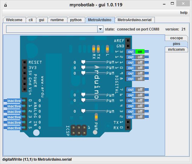
Fig. x Now on to MyRobotLab. MRL is a Java application, so you need to make sure you have Java installed. I did, but it didn't work because somehow I was running a 32 bit version of Java despite my system being 64 bit Windows. I installed the 64 bit version, and things worked a lot better! You can check to see by typing at a CMD window the line java - d64 -version. If it is not 64 bit you will get an error message, and you will need to download the 64 bit version from Java. If it is, you will see the correct version info. After you create a new directory for all this, something like E:/mrl, you download the MRL distro into it, and you execute the install by typing java -jar myrobotlab.jar. When the gui comes up, select the runtime tab, then services, then install all. This pulls in a lot of stuff, so it may take a while depending on your system and its internet connection speed. If you try to install the services before running the 64 bit version, you will get the 32 bit ones, not a good idea. Once all the services have been installed, you can right click on the Arduino Service and start an new service, calling it, say MetroArduino. Then there will appear a tab at the top also called MetroArduino. Clicking on that tab brings up the C code for the Arduino, which you can select all of that code, paste it into the arduino IDE, compile and upload it to the arduino. Of course to do this, make sure you have the right COM port selected and the right board. If you are using a Metro, select Uno as the board. This is the process for all the Arduinos you are planning on using - just make sure you've picked the right board for the service. There are several good tutorials on how to do this on Youtube, just watch the date on the videos to make sure they are talking about your version or close to it, as the procedures have changed over time. Back in MRL, you can select the MetroArduino.serial service to specify the right COM port (same one you downloaded the compiled code with) and communication between MRL and the Metro is established. Selecting the MetroArduino service and then clicking on the pins tab to the right brings up a picture of an Uno, even though its a Metro we're taliking to. Clicking on pin 13 will toggle the red LED on the Metro board, and you can see we now have full control of the Metro, shown above. Now that all the software is loaded and communicating, its time to use some scripts to make things happen. Comments may be directed to gary at liming daught org. Thanks for viewing this build log! |