|
|
|||||||
| Home |
Page 2
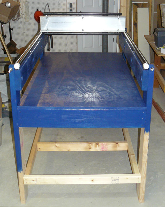
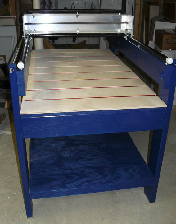
Fig. 6 With a little encouragement, the pile of lumber in Fig. 1 transformed itself into the basic table above. In addition, the black pipe rails are mounted along the sides forming the X axis, and the aluminum Y axis gantry with its own black pipe rails is just sitting on them for now so you can see how its is supposed to look. When mounting the X rails, take your time to be sure that the pipes are quite parallel, and also level along the entire length. When I first bought the pipe, I laid the best straight edge I had (a circular saw cutting guide) along the pipe and was impressed about how straight it was right from the store. After mounting it and tightening the stud nuts, I did the same trick, and there was significant light between the edge and the pipe in some places, so be careful about how you tighten the nuts. Also, sand and then oil the pipe to prevent rust and to make it as smooth as possible, especially the path along where the bearings will touch. The X pipe has some PVC caps to cover the rasp-like threads on the ends of the pipe. I was just finishing the first coat of blue when I remembered to take the picture. I realized while painting it that after I added the bottom shelf, I've made it impossible to be removed from my basement in one piece! Before the shelf, I could have stood it on end and rotated the table around the door. Now in order to get it out, I'll have to remove the bottom shelf, so I won't glue the shelf supports - just screw them in place. Shelf plywood to be added. Glued and screwed, though, it is a very stout table. With all the mass of the Y gantry, along with the Z carriage and the router, all flying around under computer control, it needs to be pretty solid.
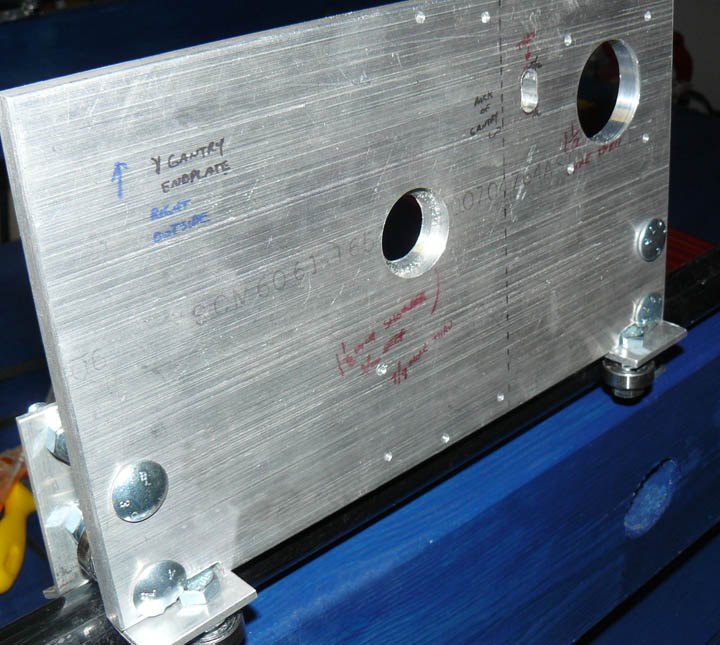
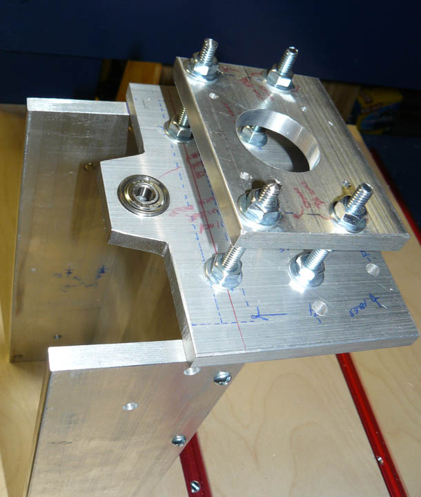
Fig. 7 Fig. 7 shows the gantry endplates have been cut and drilled, and the trucks for the X rails have been assembled for a trial fit. The large holes above were cut by my good friend and machinist extrodinaire, Frank Kerner. The other holes are just 1/8 inch placement holes that still need to be drilled out to the final diameter. If you're making one of these, mark each hole position very carefully and use an automatic center punch to start. The picture also shows another technique to prevent drilling the wrong hole - don't be bashful about using a Sharpie marker on the piece showing orientation and placement. There are many parts that are mirrored and almost (but not quite) symmetric, a warning flag to be wary about getting the part oriented correctly. The marker ink easily comes off with a swipe of lacquer thinner when the time comes. All in all, the truck bearings fit very well, and it glides on the rails with very little effort. These endplates get attached to the ends of the Y gantry beam shown in the previous picture.
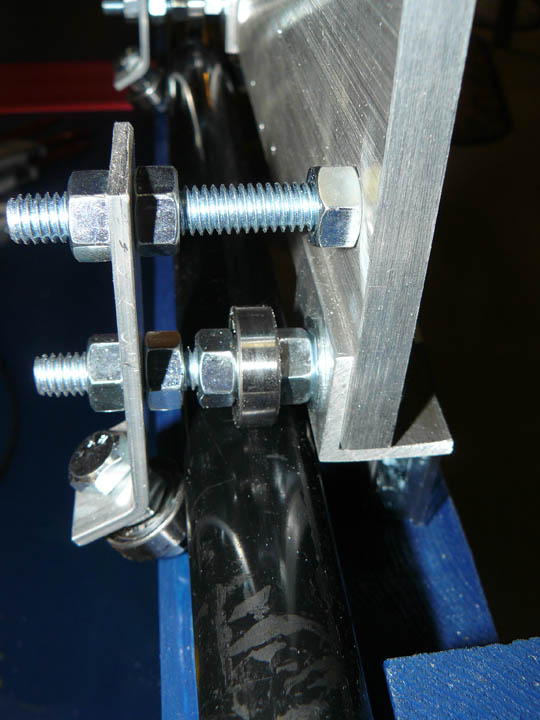
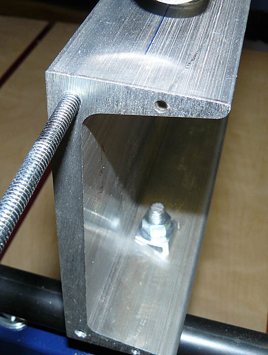
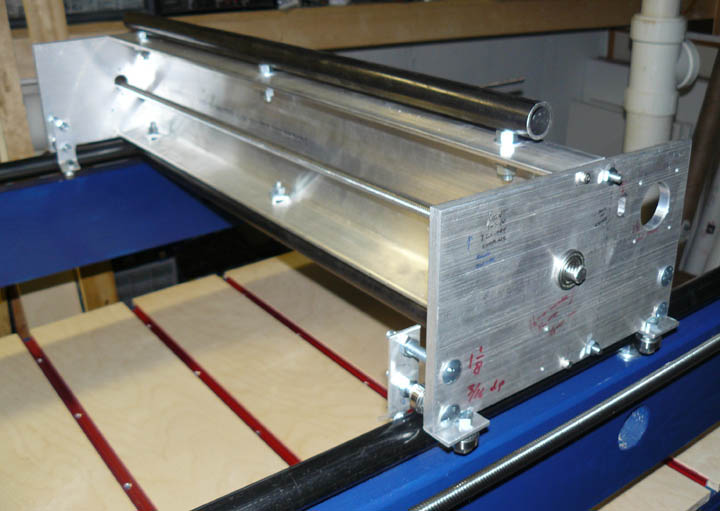
Fig. 8 shows a close-up of the end of the plate showing the X axis trucks. Three bearings make up each end plate corner that rides on the rail. You can see the uneven black paint on this rail - and that was the best of the lot at the store. In Fig. 9, the end of the Y gantry is drilled and tapped. 1/4-20 studs and 8-32 bolts will go into the holes, attaching the gantry end plates. That threaded rod is about 1 1/2 inches into the gantry end. A drill press was instrumental in drilling and tapping those holes.
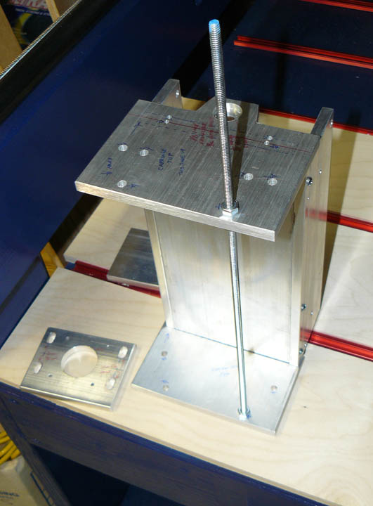
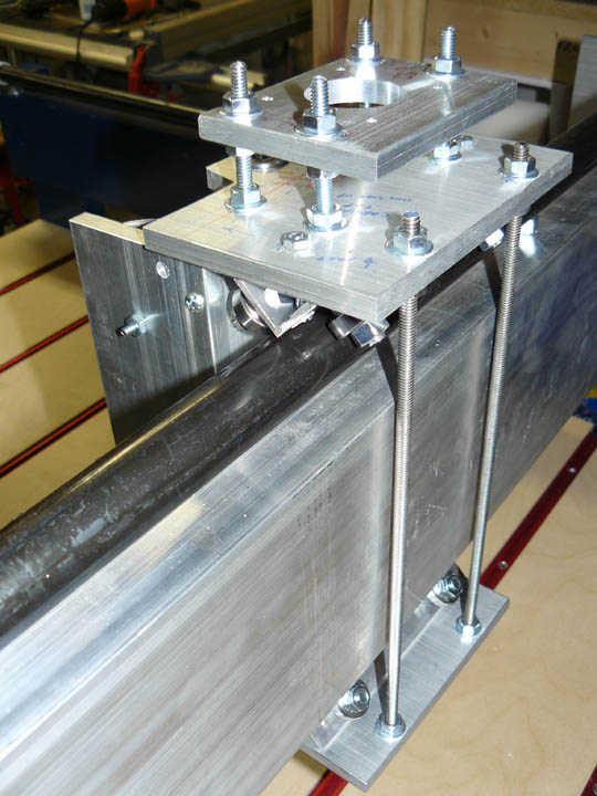
Fig. 10 Here, the X axis is about done, save mounting the stepper and drive screws with the leadnuts One of the drive screws is shown along the bottom of the screen. The Y axis screw is just laying in the holes in the center of the gantry plates. The whole gantry glides solidly on its rails with 12 ball bearings, and can be moved up and down the table with the slightest push. When final alignment is possible, all of the threaded pieces will be taken out and reapplied with Loctite.
Fig. 11 In Fig. 11, the table itself is nearly done with the bottom shelf on and the upper clamping surface in place. The T-slot tracks are usually presented going lengthwise down the table, but a 5 foot table doesn't go well with 6 foot tracks. Three foot pieces were much cheaper (per foot), and I don't see why getting the hold-down bolts on or off from the side will present any problem. I need to give the plywood pieces between the T-slot tracks a couple coats of satin Polyurethane. This is not intended to be a sacrificial surface, but allows clamping a sacrifice board, if needed, and the target piece to the table. I am not going to permanently attach the plywood, as I can then use layered shims to match the X-Y plane when the router is done. This should give me an area under the router bit of 24 by 48 inches.
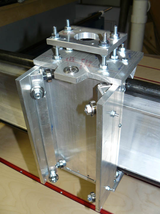
Fig. 12 shows the back of the carriage at an early stage. There are side plates, a back plate (the big one) and top and bottom plates. The side plates are fastened to the back plate by bolts through drilled and tapped holes in the back plate. Likewise, more holes are drilled and tapped in the back plate to attach the top and bottom plates. In the right photo, the stepper mount is in place on top of the the top plate. Two of the bolts go down into drilled and tapped holes into the back plate; the right hand bolts are just carriage bolts up from the top plate. The mount can slide back and forth with slotted holes to provide a tension adjustment for the stepper belt.
In Fig. 14 the carriage front is shown with the Z axis trucks oriented up and down on the side plates. The Z axis drive thread hangs down from the bearing, connected to the stepper motor shaft with pulleys and timing belt. Right, the back of the carriage shows the Y axis trucks mounted across the underside of the top plate and across the bottom plate. It also glides very smoothly. The threaded rods allow tension to be controlled on the trucks riding the rails. The carriage is both massive and busy, but it does dual duty - it serves as the object that firmly but smoothly rides across the gantry, as well as the vertical bed for the Z rails and the support for an axis motor and the router itself. The original plans call for the gantry to be made from a 2x6, and the carriage to be made from plywood. I hope that by making it from metal, it will be able to support more aggressive cuts, like those on aluminum - in that case I will need to change the speed of the router and the milling bit, as well as the feed rate and depth of cut, but I am anxious to try it! |