|
|
|||||||
| Home |
Page 3
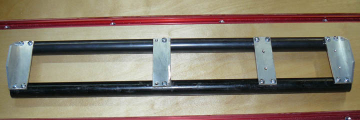
Fig. 16 Above is the Z axis assembly whose black pipe rails were cut, drilled, and tapped for the cross pieces. The rails go into the trucks in the previous photo, and the whole assembly is supported by the leadnut.
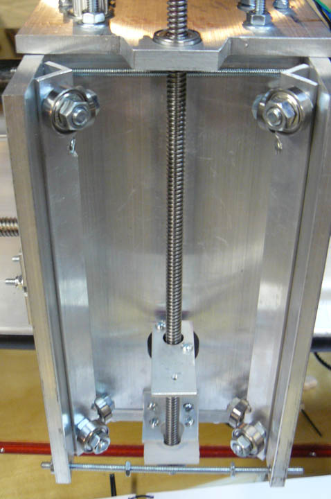
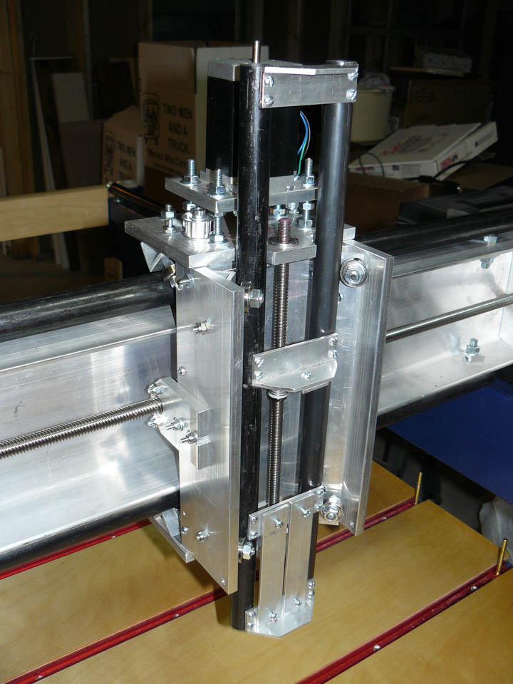
Fig. 17 shows the Z axis drive screw with the leadnut mounted in the carriage, with the trucks for the Z axis rails installed. In Fig. 18 the Z axis is just about done, with the rails inside the trucks, and the cross bracing and router mounting strips on the bottom. On the left of the carriage is the leadnut in place on the Y axis screw. From this point until I'm actually cutting something (I'll have to figure out how to post movies!) the project has entered the phase where there is still a lot of work to be done, but not much of it is easily visible when it's completed.
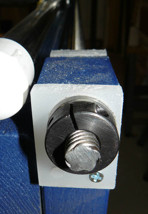
Fig. 19 The above shows the end of one of the X axis drive screws. You can clearly see there are 5 threads cut into this rod. There are 2 screws on each side of the table, therefore 4 rod ends to support. On each rod end there are 2 bearings, both cased in the polycarbonate cut earlier. The reason for having the two separated bearings per rod end is to help prevent "whipping" or bending the rod during rapid movements of the gantry. On the end shown above is a black clamping collar, and on the opposite end is a pulley, which is driven via a non-slip timing belt by the stepper motors. Stepper motors usually move 1.8 degrees per step, as do the Xylotex motors. This means that it takes 200 steps to move the motor shaft one full revolution. However, the Gecko drivers have a nice ability known as micro stepping - that is, it can move the stepper motor in fractions of its native step. They can electrically pulse the motors accurately in 1/10 of these native steps, making the same motor require 2000 pulses per revolution. The ACME threaded rod for the X and Y axes have 10 threads per inch, divided by the 5 threads, which means it will take two full revolutions of the rod to make a nut traveling across it move 1 inch. Inversely, it will move the nut 0.5 inches per revolution of the motor. (The timing belt and pulleys between the motor and the rods is on a 1:1 ratio, so there is no mechanical advantage there.) Since it takes 2000 pulses to make it go one revolution, it takes 4000 pulses to go one inch, or 0.00025 inches per pulse! This means that the theoretical accuracy I should get from this arrangement is one-quarter of a thousandth of an inch! I said theoretical because some factors, especially backlash and structural rigidity, will lower this some. I am anxious to do some testing when it is done, but I will be very happy to see the machine demonstrate control of a cutting bit to the nearest couple of thousandths! Another thing this means is that the computer will be quite busy generating all those pulses, especially when three axes are moved together. I will need to make sure the XP system has a lot of its background tasks turned off when running Mach3. Mach3 actually includes a program that shows you a nice little window that measures the background "noise" or extraneous interrupts to see if your system can handle the interrupt load. You especially don't want some virus checker or network task to suddenly begin running while in the middle of a carve!
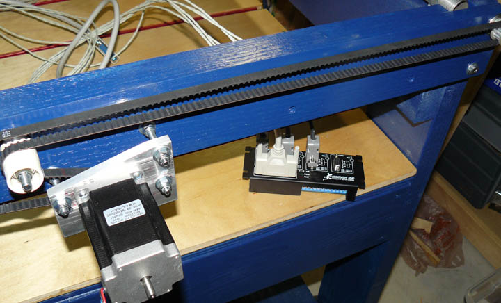
Fig. 20 Above shows the other end of the table, with the X axis stepper motor, its timing pulley and belt mounted on a cross piece. The plans call for the cross piece to be a 1x4 lumber, but I used 2 1x4s of oak and glued and screwed them together. The belt rotates on an idler pulley, made from some 608 bearings and a 1/2 inch PVC irrigation pipe coupler. The whole motor mount rotates around the upper right bolt, providing belt tension. The belt wraps around the pulleys on the end of each X drive screw. On the table is the Gecko 540, with the cables made up to go to each motor, and the parallel cable to go to the computer's port. All of those cables are shielded, and will be grounded to a single common point.
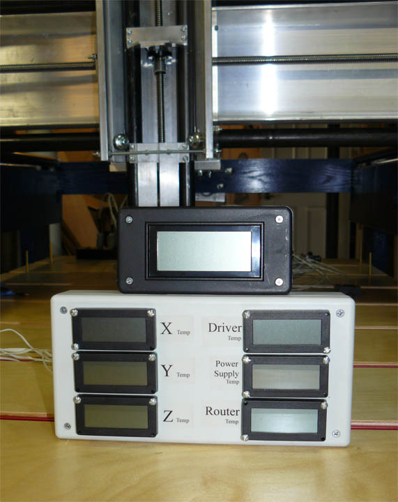
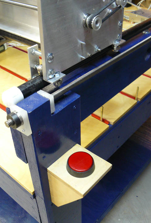
Fig 21 - I have read where builders are concerned about the temperature some of the components while in extended operation. I stumbled upon these LCD thermometers for $4 a piece, so maybe 6 of them is a little over kill, but for $24 there won't be much of a question about it now. The above shows my monitor display - the 6 LCDs each have a thermistor that is physically attached to the 6 table components as labeled: one for each stepper motor, and one for the power supply, router, and driver. The top box is an LCD panel meter ($9.50) to monitor the power supply voltage, and with a longer probe, it will help to troubleshoot voltages on the table. All are mounted in a cheap plastic "project box." Anyway, I'll mount this near the power supply and driver. Fig. 22 shows the E-stop button mounted on the side of the table, made with some Baltic birch plywood scrap. These machines can be dangerous in operation and have been known to cause injury to both operator and machine, so being able to shut it all down with one button is a good safety feature. Because of this, I will use a solid state relay to put the router itself under software control. Also, the e-switch button is lit up when the system is on, helping me to remember to turn it off when not in use.
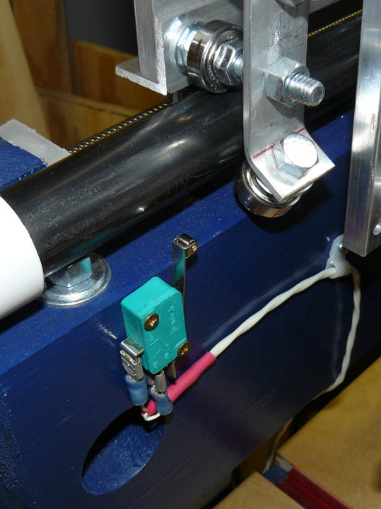
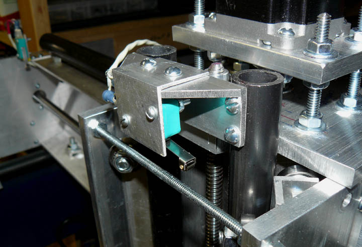
Although some builders don't use limit switches because travel limits can be imposed in the Mach3 software, I want to install them. These are placed at both extreme ends of each axis to prevent a mistaken program (or operator!) from trying to make the stepper motors move the gantry or carriages right off its rails. Above, Fig. 23 shows one of the X axis limit switches, and Fig. 24 shows one of the Y axis limit switches. The limit switches for each axis are wired in series to the normally closed positions on the switches. If either one of them is tripped, a signal occurs and everything shuts down. In this respect, they function much like the E-stop switch. Since the software knows the direction of travel that caused the limit violation, by using two switches per axis it knows which way to back off. All this is in addition to software limits - when you configure Mach 3 you tell it the maximum travel for all axes, and it also makes sure it doesn't go beyond limits, but Windows apps sure have been to known to lose their thread.
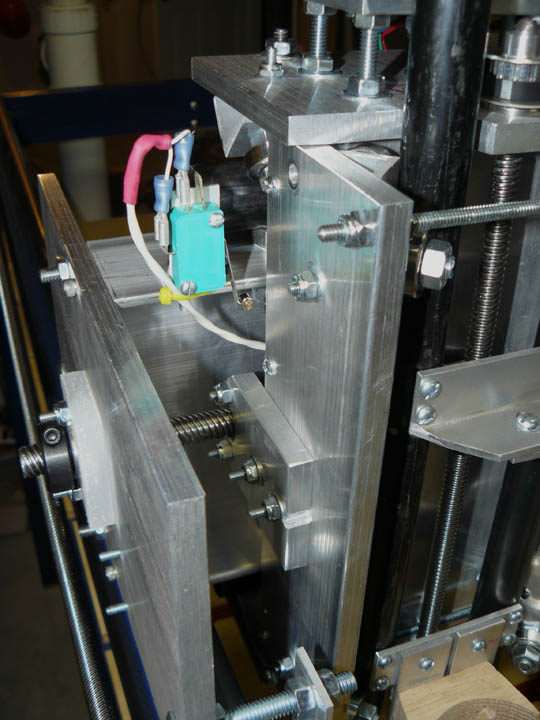
Fig. 25 This is the Z axis limit switch, mounted on a bracket that is attached to the top cross brace. Here the Z axis is lowered about a half inch away from its limit, where the switch roller will make contact with the top tension adjustment rod. In the upper left corner is the limit switch also shown in Fig. 24. |
||||||